Scanning uv-led exposure device

A technology of UV-LED and exposure device, which is applied in the direction of photolithography exposure device, microlithography exposure equipment, etc., which can solve the problems of irregular scanning speed, the need to perform warm-up preparatory actions, and reduce product yield.

Inactive Publication Date: 2016-01-20
NAT CENT UNIV
View PDF5 Cites 0 Cited by
  • Summary
  • Abstract
  • Description
  • Claims
  • Application Information

AI Technical Summary

Problems solved by technology

[0002] In the past, the exposure machine of the non-UV-LED system was large, and the production space was also large, resulting in a relatively high investment cost.
However, in the current exposure machines that use ultraviolet (UV) exposure, the exposure process is not specially improved. The exposure light source adopts divided area exposure for the exposure target area. When the light source moves in different divided areas, the movement must be repeated. The action of light source→braking→moving the light source is likely to cause instability of the UV light source due to irregular scanning speed, and this method for a certain LED exposure position is also likely to cause insufficient irradiance and insufficient exposure uniformity. problem, thereby reducing the product yield; in addition, when the known technology is used for the exposure process, the light source needs to be turned on all the time, so the life of the UV light source is short. As for the light source on / off (ON / OFF) is not easy to control
[0003] In view of the lack of uniformity of the overlapped lighting area of ​​the light source in the known technology, it generally cannot meet the needs of users to achieve the purpose of increasing exposure uniformity and improving energy efficiency in actual use.

Method used


Image

  • Scanning uv-led exposure device
  • Scanning uv-led exposure device
  • Scanning uv-led exposure device

Examples


Embodiment Construction

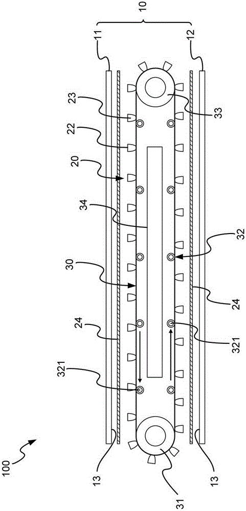
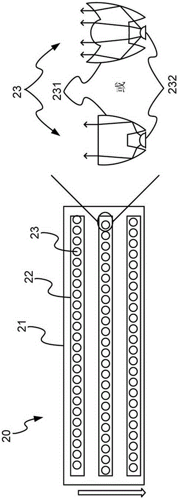
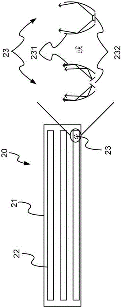
[0034] see Figure 1 to Figure 3 Shown are a schematic structural view of the present invention, a schematic top view of a UV-LED lighting unit according to a specific embodiment of the present invention, and a schematic top view of a UV-LED lighting unit according to another specific embodiment of the present invention. As shown in the figure: the present invention is a scanning UV-LED exposure device, which is an LED exposure machine with the function of large-area divided area exposure. The target exposure area for projection irradiation. The scanning UV-LED exposure device 100 at least includes an exposure unit 10 , a UV-LED lighting unit 20 and a cycle moving ring 30 .

[0035] The above-mentioned exposure unit 10 includes a set of upper exposure stage 11 and lower exposure stage 12 spaced apart from each other. The corresponding two planes are used to place a substrate (not shown) coated with a photoresist layer. The resist layer is made of photosensitive material and ...


PUM


Abstract

The invention relates to a scanning UV-LED (Ultraviolet Light Emitting Diode) exposure device, which comprises an exposure unit, an UV-LED illumination unit and a circulating periodic moving ring. According to the scanning UV-LED exposure device, anUV-LED exposure light source doing periodic circulation at a fixed velocity is used, and in the scanning exposure process in a large-area target region, the moving does not need to stop; the goal of improving the use efficiency of energy through constantly, circularly and repeatedly utilizing the exposure light source is achieved; in addition, the radiant illumination uniformity of an LED array light source is enhanced through staggered arrangement, so that the exposure uniformity is improved, and further, the qualification rate of products is effectively improved. In addition, through structural designs of upper and lower exposure platforms and the circulating periodic moving ring, the size of the device can be reduced; the production space and the energy consumption are reduced, so that the production cost is reduced; the circulating periodic moving ring is used for driving the LED array light source, so that a workpiece can sufficiently utilize the space between the upper and lower exposure platforms and the circulating periodic moving ring, and the exposure of the upper and lower exposure platforms can be simultaneously carried out; energy sources can be saved; and in addition, the production speed can be effectively and relatively increased, so that the productive efficiency is improved.

Description

technical field [0001] The present invention relates to a scanning UV-LED exposure device, especially to an LED exposure machine with the function of large-area segmented area exposure, especially to a UV-LED exposure light source that cycles at a fixed rate. The target area does not need to stop moving during the scanning exposure process, so that the exposure light source can be continuously recycled and reused to increase energy efficiency and increase exposure uniformity. Background technique [0002] In the past, the exposure machines of non-UV-LED systems were large and occupied a large amount of production space, resulting in relatively increased investment costs. However, in the current exposure machines that use ultraviolet (UV) exposure, the exposure process is not specially improved. The exposure light source adopts divided area exposure for the exposure target area. When the light source moves in different divided areas, the movement must be repeated. The action...

Claims


Application Information

Patent Timeline
Patent Type & Authority Patents(China)
IPC IPC(8): G03F7/20
Inventor 陈奇夆
Owner NAT CENT UNIV
Why Eureka
Try Eureka