On board inert gas generation system

An inert gas, generation system technology, used in inert gas generation, aircraft parts, air handling equipment, etc., can solve problems such as motor inefficiency, speed limitation, etc.

Inactive Publication Date: 2014-10-01
EATON CORP
View PDF6 Cites 11 Cited by
  • Summary
  • Abstract
  • Description
  • Claims
  • Application Information

AI Technical Summary

Problems solved by technology

This is an inefficient use of the motor, which occurs because when using a centrifugal compressor, the motor speed is severely limited due to surge constraints

Method used


Image

  • On board inert gas generation system
  • On board inert gas generation system
  • On board inert gas generation system

Examples


Embodiment Construction

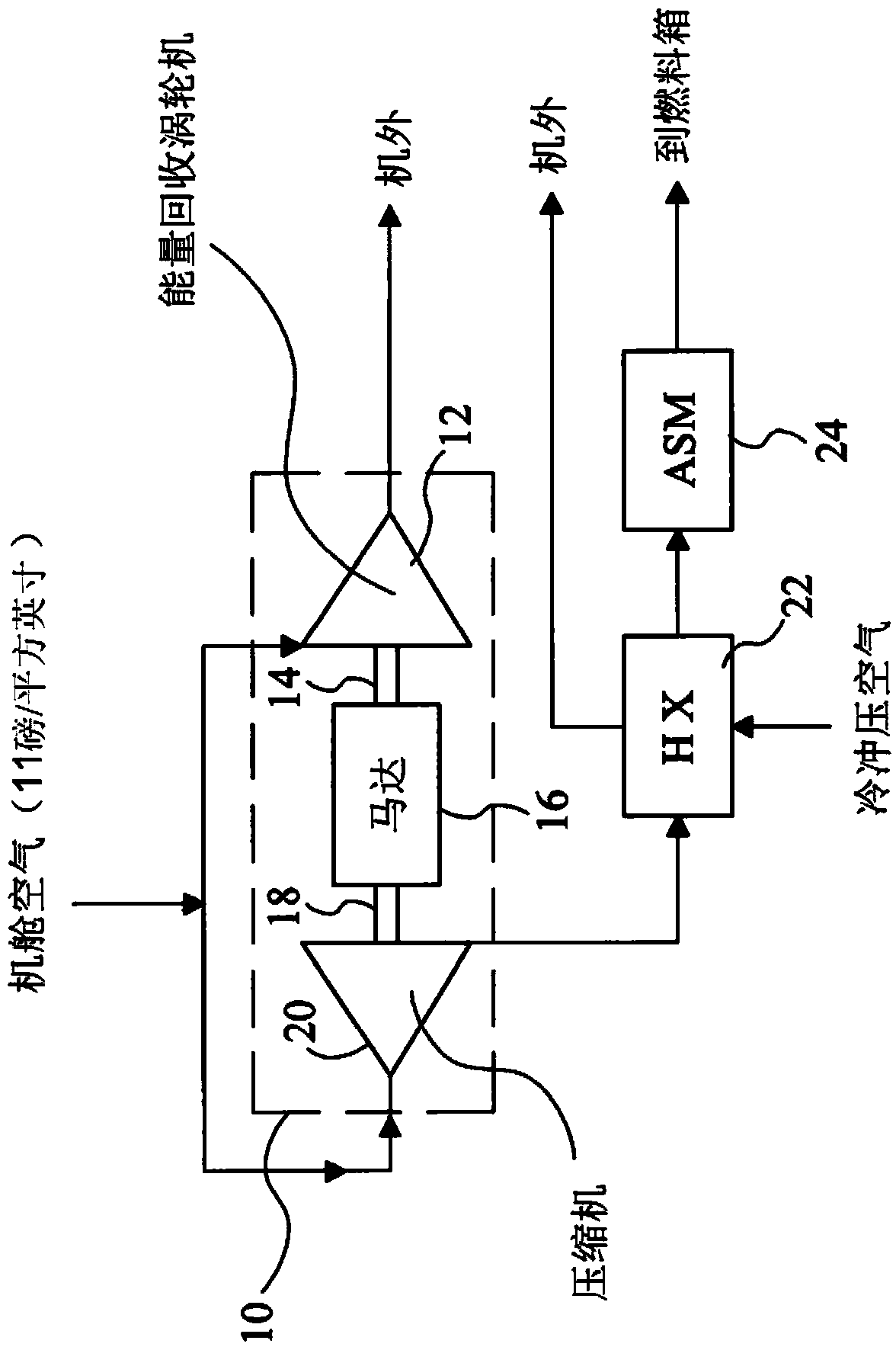
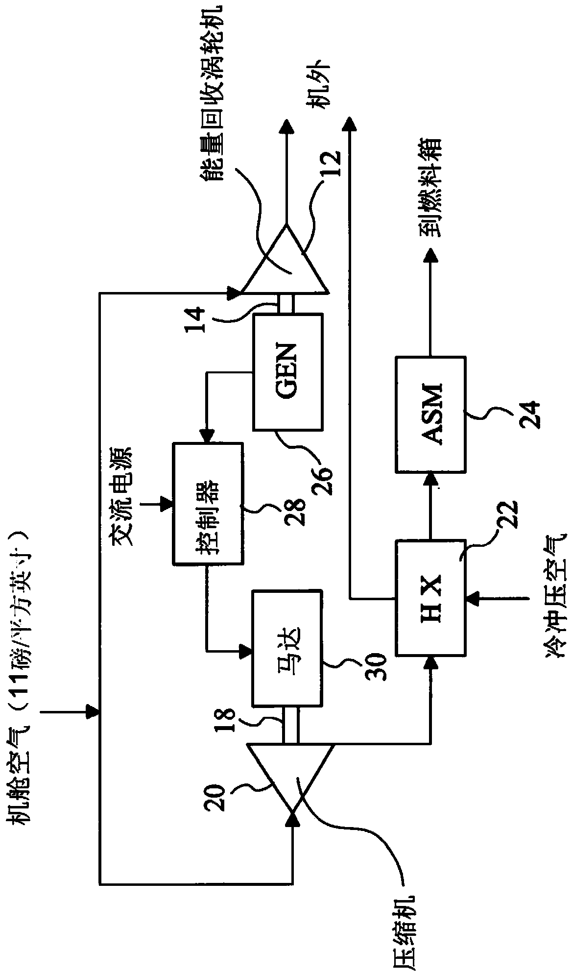
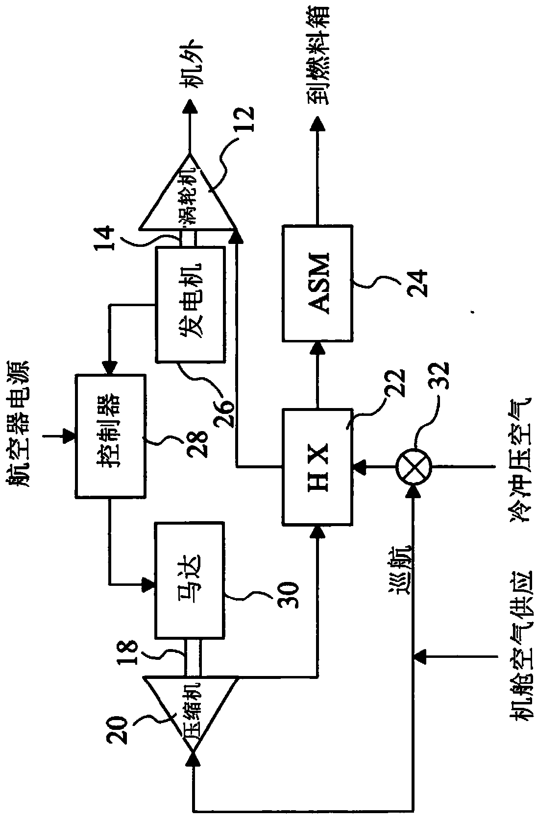
[0045] The embodiments described below employ mechanically and / or electrically driven variable speed positive displacement booster compressors to supply air to the gas separation module at the appropriate pressure and flow to inert the aircraft's fuel tanks. An energy recovery turbine is integrated with the compressor to reduce electricity consumption by supplying cabin air to the compressor and turbine.

[0046] These embodiments use cabin air provided by the aircraft's environmental control system (ECS), which requires power from the propulsion engines and increases the specific fuel consumption of the engines. After the air is circulated in the cabin, it is discharged to the atmosphere as exhaust gas through the external exhaust valve. Using this air for fuel tank inerting purposes does not cause an additional increase in Specific Fuel Consumption (SFC), since the required energy is already taken up by the ECS. Cabin pressure is typically 11 or 12 psi at cruising altitude,...


PUM


Abstract

An on board inert gas generation system for an aircraft receives air from a relatively low pressure source such as low pressure engine bleed air or ram air and passes it to a positive displacement compressor (20) to increase the pressure thereof to be suitable for supply to an air separation module (24). The speed of the positive displacement compressor may be adjusted across a wide range in order to provide efficient operation in cruise and descent phases of aircraft flight. The operating speed of the compressor and / or the flow rate from the ASM to the space to be inerted may be controlled in accordance with at least one of the gas composition in the space to be inerted, the flight condition, and the ullage volume.

Description

technical field [0001] The present invention relates to an onboard inert gas generation system for generating inert gas on board an aircraft to facilitate the inertization of fuel tanks and other areas on the aircraft. Background technique [0002] Widely accepted technical terms are used in this specification, wherein the term 'inert gas generation' means generation of an oxygen-deficient or 'nitrogen-enriched atmosphere' (NEA). The recent trend to construct aircraft wings from composite materials means that due to the lower thermal conductivity of composite materials, the temperature inside the fuel tank can be higher than that of wings made of traditional materials. Therefore, due to the high temperatures experienced, there is an increased need to efficiently inert aircraft fuel tanks in composite wings. It is known to use one or more filters or 'gas separation modules' (ASM) which allow the separation of the incoming feed gas into a nitrogen-enriched gas (NEA) fraction ...

Claims


Application Information

Patent Timeline
Patent Type & Authority Applications(China)
IPC IPC(8): B64D37/32B64D13/06B01J19/14
CPCB64D2013/0677B64D37/32B01J19/14B01D53/00B01J2219/00162
Inventor A·E·梅西A·达斯M·P·乔希K·K·玛哈尔塔卡尔H·K·P·K·科利帕拉
Owner EATON CORP
Why Eureka
Try Eureka