Communication optical fiber cable well and method for constructing communication optical fiber cable well
A communication optical cable and construction method technology, which is applied in artificial islands, water conservancy projects, infrastructure engineering, etc., can solve the problems that the construction period of communication optical cable wells cannot meet customer requirements, etc., so as to prevent cracking or displacement, facilitate processing, and avoid damage. pressure effect
- Summary
- Abstract
- Description
- Claims
- Application Information
AI Technical Summary
Problems solved by technology
Method used
Image

Examples
Embodiment 1
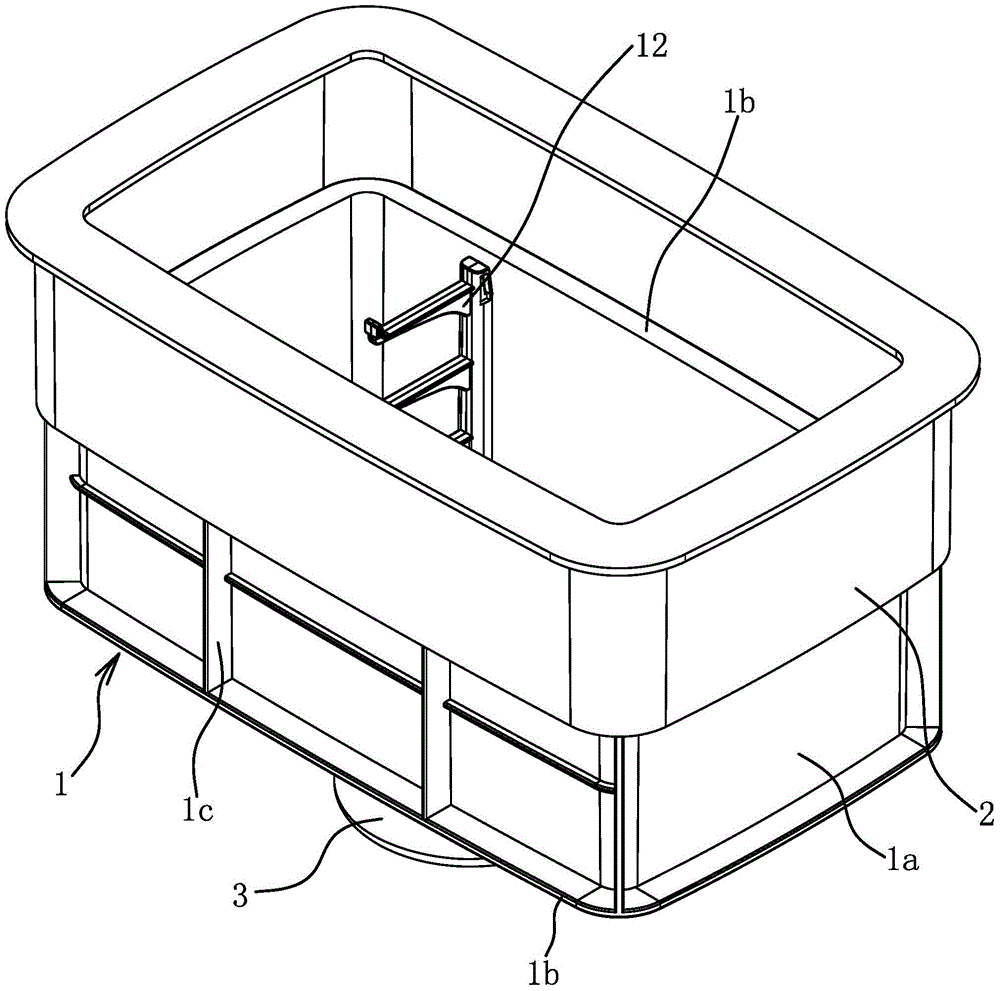
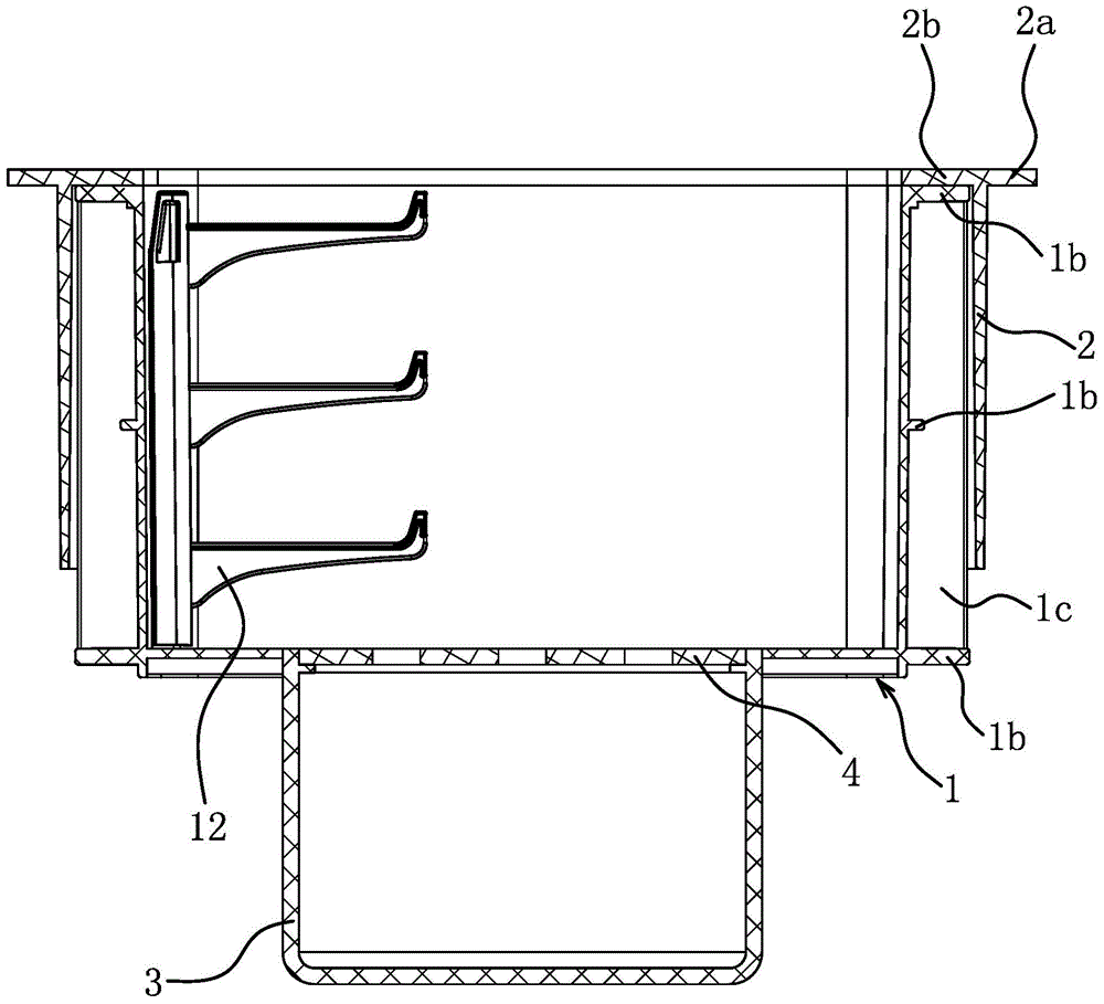
[0040] Such as figure 1 and figure 2 As shown, the communication optical cable well includes a bottom well 1, a lifting casing 2 and a water storage barrel 3. The side wall of the bottom shaft 1 has a connection area 1a. The lifting casing 2 is slightly larger than the bottom shaft 1 so that the lifting casing 2 can be set outside the bottom shaft 1 and can go up and down. The shape of the lifting casing 2 and the bottom shaft 1 is identical to ensure that the lifting casing 2 is set on the bottom shaft 1, and the circumferential gap size between the inner wall of the lifting casing 2 and the outer wall of the bottom shaft 1 is consistent. Such as figure 1 and figure 2 As shown, the cross-sectional shape of the lifting casing 2 and the bottom shaft 1 is a rectangle.
[0041] The gap between the lifting casing 2 and the bottom shaft 1 is not more than 8mm. This value can not only ensure that the lifting casing 2 can be conveniently placed outside the bottom shaft 1, but ...
Embodiment 2
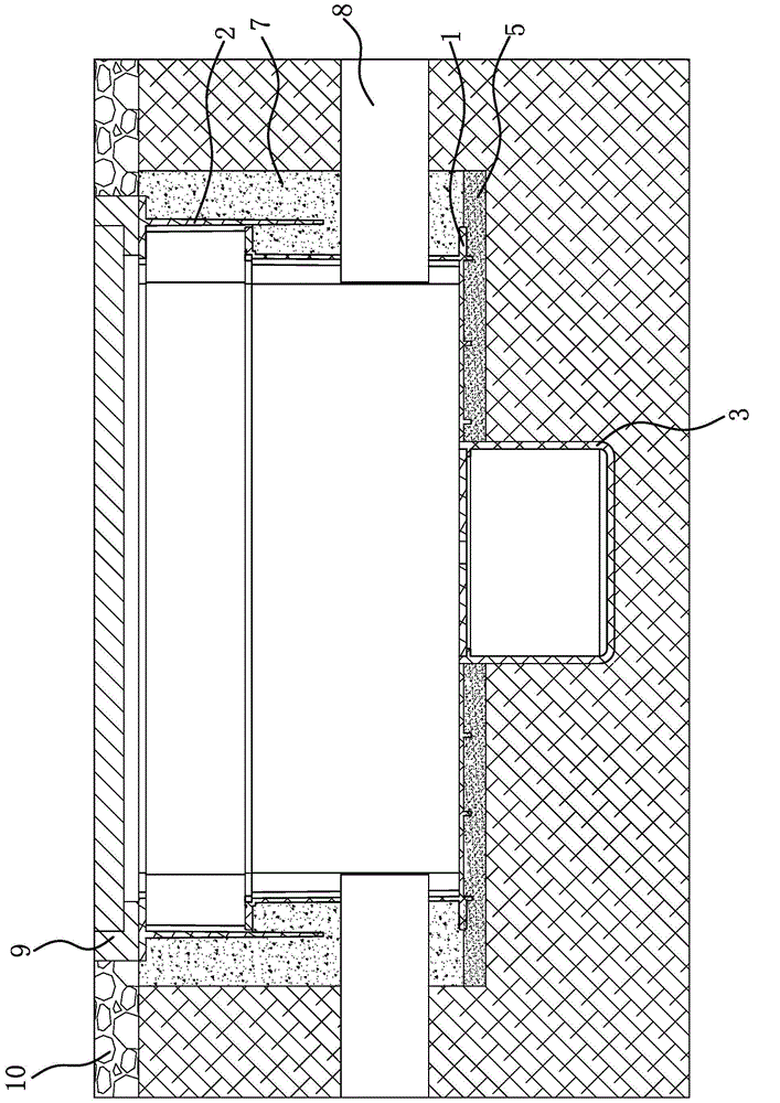
[0054] The structure and principle of this embodiment are basically the same as that of Embodiment 1, the difference is: after the communication optical cable pipe 8 passes through the hole in the side wall of the bottom shaft 1, then between the communication optical cable pipe 8 and the side wall of the bottom shaft 1 Filled with sealant, the structure and process can significantly reduce the amount of water infiltration.
Embodiment 3
[0056] The structure and principle of this embodiment are basically the same as that of Embodiment 1, the difference is that: Figure 5 and Figure 6 As shown, the communication optical cable shaft also includes a takeover sealing ring 11 made of rubber. The outer surface of the takeover sealing ring 11 has an annular sealing groove 11a, and one end of the takeover sealing ring 11 is a constricted sealing lip 11b.
[0057] Take over the sealing ring 11 in the construction method of the communication optical cable well, and install between the hole that is drilled on the side wall of the bottom shaft 1 and the hole that the communication optical cable pipe 8 passes through the side wall of the bottom shaft 1 . In other words, first put the connecting pipe sealing ring 11 through the hole opened on the side wall of the bottom shaft 1, and the edge of the hole in the side wall of the bottom shaft 1 is embedded in the annular sealing groove 11a, so that the connecting pipe sealin...
PUM
 Abstract
Description
Claims
Application Information
 - R&D
- Intellectual Property
- Life Sciences
- Materials
- Tech Scout
- Unparalleled Data Quality
- Higher Quality Content
- 60% Fewer Hallucinations
Browse by: Latest US Patents, China's latest patents, Technical Efficacy Thesaurus, Application Domain, Technology Topic, Popular Technical Reports.
© 2025 PatSnap. All rights reserved.Legal|Privacy policy|Modern Slavery Act Transparency Statement|Sitemap|About US| Contact US: help@patsnap.com