Fully-sealed power distribution cabinet

A power distribution cabinet, fully sealed technology, applied in the substation/power distribution device shell, busbar/line layout, etc., can solve the problems of dust accumulation in the power distribution cabinet, time-consuming, obstacles, etc., to achieve convenient adjustment, easy search, The effect of improving performance

Inactive Publication Date: 2014-10-08
SHANGHAI HAIBIN ELECTRICAL
View PDF7 Cites 12 Cited by
  • Summary
  • Abstract
  • Description
  • Claims
  • Application Information

AI Technical Summary

Problems solved by technology

[0004] For the above-mentioned power distribution cabinet, in extreme weather conditions and accidents such as flooding, the inlet holes and cable joints on the ordinary power distribution cabinet cannot achieve a complete sealing effect, which will cause the electrical components in the power distribution cabinet to be flooded. Sealing the wire inlet hole of the electric cabinet is a problem that needs to be solv

Method used


Image

  • Fully-sealed power distribution cabinet
  • Fully-sealed power distribution cabinet
  • Fully-sealed power distribution cabinet

Examples


Embodiment Construction

[0026] The present invention will be further described in detail below in conjunction with the accompanying drawings and embodiments.

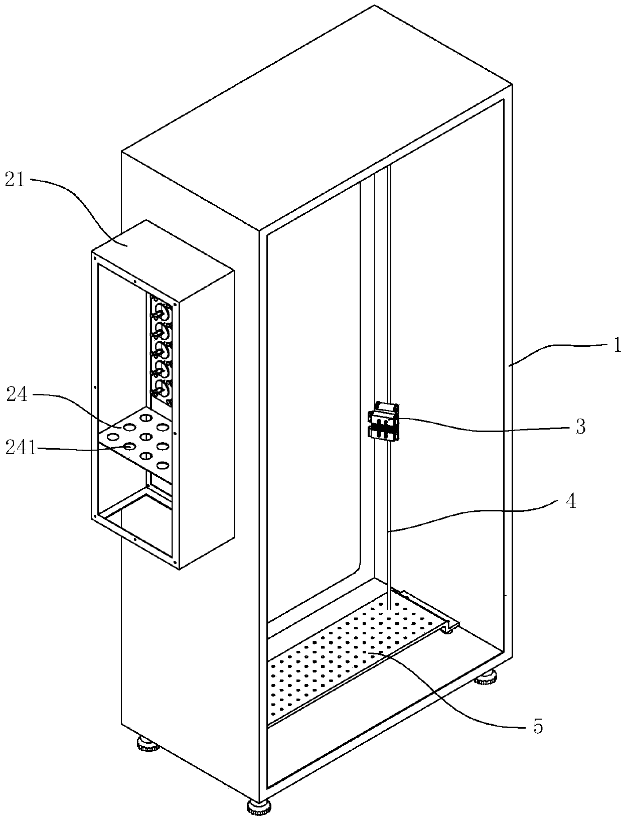
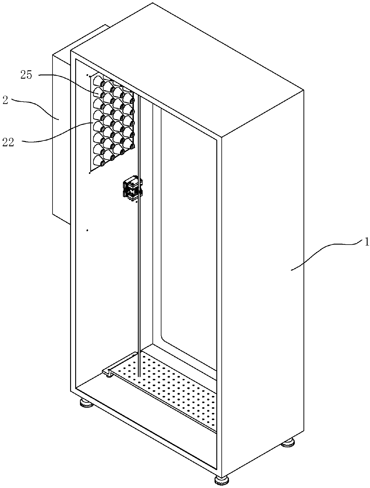
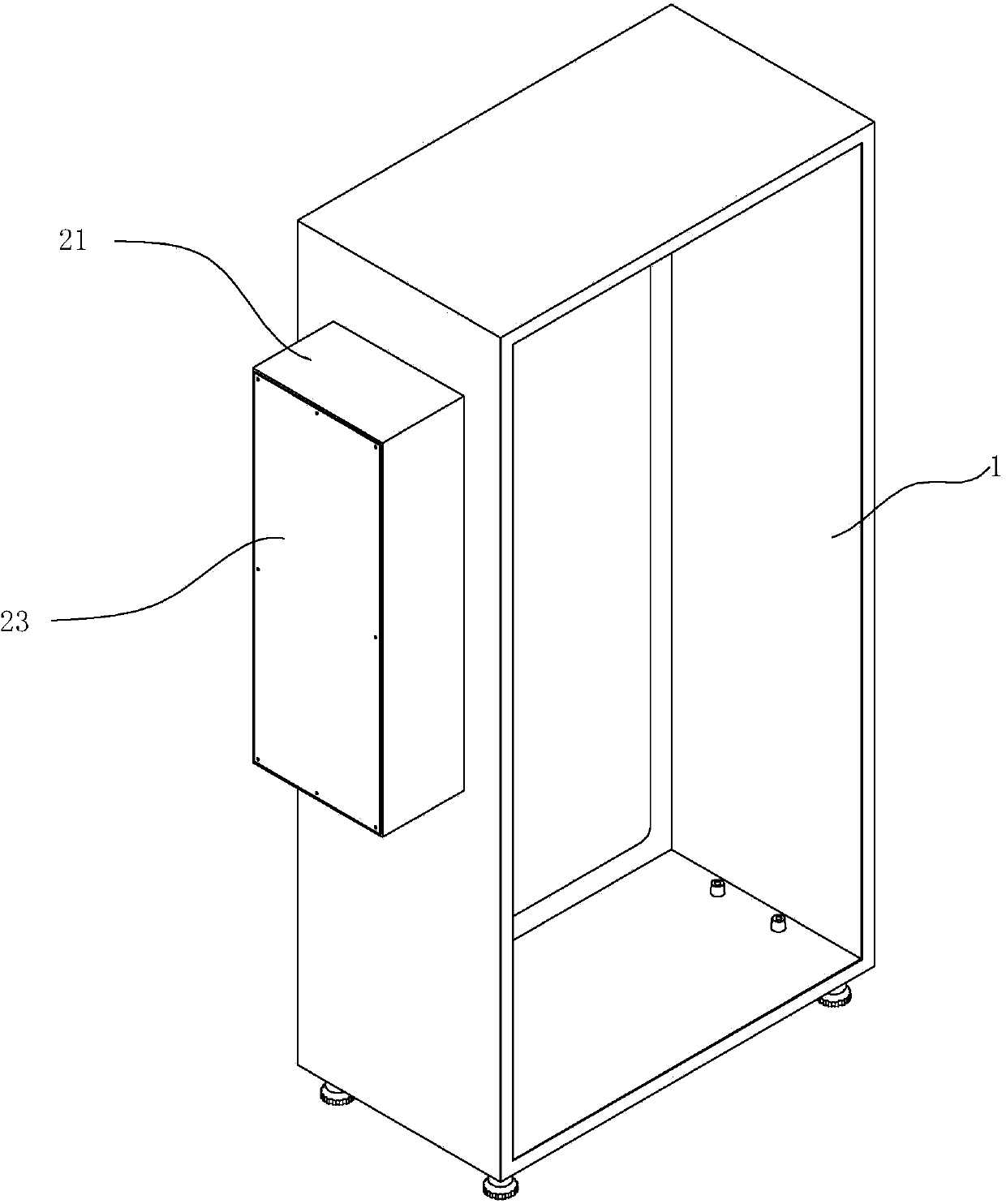
[0027] see Figure 1 ~ Figure 3 , a fully sealed power distribution cabinet, including a cabinet body 1 and a cabinet door (not shown), when the cabinet door is closed, it is sealed with the cabinet body 1 with a rubber seal. The side of the cabinet body 1 is provided with an incoming line box 2 . The terminal box 2 includes a box body surrounded by four side plates 21, a bottom plate 22 and a sealing plate 23 opposite to the bottom plate 22. The lower end of the terminal box 2 is open so that cables and wires enter the terminal box 2. The position corresponding to the bottom plate 22 of the incoming line box 2 is opened on the side wall of the cabinet body 1, so that the bottom plate 22 is installed. A pipe joint mounting plate 24 is arranged inside the wire inlet box 2, and a plurality of mounting holes 241 are opened on the pipe joint mou...


PUM


Abstract

The invention discloses a fully-sealed power distribution cabinet comprising a cabinet body. A wire inlet box is arranged in one side of the cabinet body, and the wire inlet box includes a bottom plate arranged on the side of the cabinet body. The bottom plate is provided with a plurality of holes, one side, facing the inside of the cabinet body, of the bottom plate is fixedly connected with conical tubes with two open ends, and the conical tubes gradually narrow toward the inside the cabinet body. Cable wire sealing rubber plugs are arranged in the conical tubes. Each of the cable wire sealing rubber plugs includes two ejector pins, semi-circular first and second end plates are arranged on each ejector pin at intervals, the second end plates are disposed at the tail ends of the ejector pins, and the outer diameter of the two first end plates after the two first end plates are combined is matched with the inner diameter of the holes. Each ejector pin is provided with a rubber plug which is disposed between the first end plate and the second end plate, the opposite surfaces of two rubber plugs are provided with threading grooves which gradually narrow toward the inside the cabinet body and allow a cable wire to pass through, and the shape formed by two rubber plugs is matched with the conical tubes.

Description

technical field [0001] The invention relates to a power distribution cabinet, in particular to a fully sealed power distribution cabinet. Background technique [0002] The existing cables and wires in the power distribution cabinet on the market are generally fixed and guided by ordinary wire grooves. All the cables and wires outside the power distribution cabinet usually pass through corrugated hoses and installations from one to several round holes. The cable joints on the side panel of the electric cabinet are passed into the distribution cabinet in strands, and then guided to the vicinity of the corresponding electrical components through the horizontal and vertical wire grooves. [0003] For example, a Chinese patent application with application number 201110367812.6 discloses a photoelectric separation integrated power distribution cabinet for optical fiber composite low-voltage cables, including a cabinet body, a power distribution unit arranged at the lower end of th...

Claims


Application Information

Patent Timeline
IPC IPC(8): H02B1/28H02B1/20
Inventor 祝元王锡痒
Owner SHANGHAI HAIBIN ELECTRICAL
Why Eureka
Try Eureka