Ejection pressurizing type sleeve gas recovery device

A technology for recovering device and casing gas, which is applied in the production of fluids, wellbore/well components, and earth-moving drilling, etc. It can solve the problems of lowering the effective production pressure drop of oil wells, affecting pump efficiency, and large power consumption, avoiding environmental problems. Pollution and waste, ease of installation and transportation, effect of improving plant utilization

Active Publication Date: 2014-10-15
CHINA UNIV OF PETROLEUM (EAST CHINA)
View PDF3 Cites 5 Cited by
  • Summary
  • Abstract
  • Description
  • Claims
  • Application Information

AI Technical Summary

Problems solved by technology

[0002] In oilfield crude oil extraction, as the pressure of reservoir fluid decreases, light components in crude oil, such as methane, ethane, propane, etc., will volatilize from the annular space between casing and tubing to form casing gas. A gas column with a certain pressure is formed, which forces the dynamic liquid level of the oil well to drop, so that the effective production pressure drop of the oil well is reduced, and the production capacity is reduced; a part of the gas enters the pump cavity with the liquid flow, occupies a certain space in the pump cavity, and affects the pump efficiency. "Air lock" occurs, making the well pump unable to work
[0003] Due to the low output of oil well casing gas and the unstable pressure, there is no special gas pipeline to transport casing gas, and the casing gas cannot be recovered and utilized effectively. Strip burning or directly exhaust the casing gas
[0004] In order to solve this problem, there are currently three methods for recovering casing gas: one is to use the power of the pumping unit itself to drive the plunger to recover the casing gas, and pressurize it to enter the wellhead pipeline; this device has a complex structure, and Only suitable for pumping unit oil production, not for submersible pump oil production
The other is to use an air compressor device to increase the pressure of the casing gas, separate the gas from the liquid, and treat the harmful gas before entering the gas storage tank; this method has large investment, high maintenance and management costs, and large power consumption, which is economical. The benefit is not obvious, so it has not been promoted and applied

Method used


Image

  • Ejection pressurizing type sleeve gas recovery device

Examples


Embodiment Construction

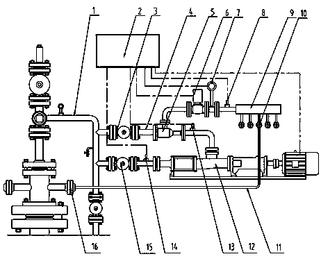
[0012] The structure and implementation of the present invention will be described in detail below in conjunction with the accompanying drawings.

[0013] Part of the crude oil extracted from the oil well enters the device from the upstream of the oil outlet pipeline (1) through the liquid inlet valve (3). After the crude oil flows through the nozzle of the ejector (5), due to the conversion of pressure energy into velocity energy, A vacuum negative pressure chamber is formed, and the casing gas collected in the gas storage tank (9) is sucked into the negative pressure chamber, and the crude oil and the casing gas reach a stable flow state after being mixed and diffused by the diffuser. Due to the pressure drop caused by gas-liquid mixing, the pressure of the mixed fluid is lower than the pressure in the oil outlet pipeline (1), so it is necessary to input the mixed fluid into the gas-liquid mixed delivery pump (12) to increase the pressure to meet the normal delivery pressure ...


PUM


Abstract

The invention provides an ejection pressurizing type sleeve gas recovery device which is used for recovering sleeve gas in a wellhead of an oil field. The ejection pressurizing type sleeve gas recovery device comprises an ejector, a gas-liquid mixing and conveying pump, a liquid inlet valve, a liquid outlet valve, gas inlet valves, a gas storage tank, a gas pressure sensor, a gas flow meter, an electric valve, a control unit and the like, and is integrally manufactured into a skid-mounted block. A liquid inlet opening of the ejector is connected with the upstream part of an oil outlet pipeline of an oil well, and a liquid outlet opening of the ejector is connected with an inlet of the gas-liquid mixing and conveying pump. When the ejection pressurizing type sleeve gas recovery device works normally, the liquid inlet valve and the liquid outlet valve are both opened; when the pressure of the sleeve gas reaches a certain value, the gas pressure sensor transmits a signal to the control unit, the control unit sends an instruction to start the gas-liquid mixing and conveying pump, and the electric valve is opened in a delayed mode; liquid which flows at a high speed in the ejector sucks in the sleeve gas, the liquid and the sleeve gas are mixed to enter the liquid-gas mixing and conveying pump to be pressurized, and then are conveyed into the oil outlet pipeline of the oil well, the sleeve gas can be recovered, and the situation that waste of energy sources and air pollution are caused by combustion or emptying of the sleeve gas is avoided.

Description

technical field [0001] The invention relates to an injection pressurized casing gas recovery device, which is used for recovering the casing gas produced in the process of oil recovery in an oil field. Background technique [0002] In oilfield crude oil extraction, as the pressure of reservoir fluid decreases, light components in crude oil, such as methane, ethane, propane, etc., will volatilize from the annular space between casing and tubing to form casing gas. A gas column with a certain pressure is formed, which forces the dynamic liquid level of the oil well to drop, so that the effective production pressure drop of the oil well is reduced, and the production capacity is reduced; a part of the gas enters the pump cavity with the liquid flow, occupies a certain space in the pump cavity, and affects the pump efficiency. An "air lock" occurs, making the oil well pump inoperable. [0003] Due to the low output of oil well casing gas and the unstable pressure, there is no s...

Claims


Application Information

Patent Timeline
Patent Type & Authority Applications(China)
IPC IPC(8): E21B43/00
Inventor 赵军友王秀会王少波孙乾刘祥猛万法伟孙晓山张蕊蕊
Owner CHINA UNIV OF PETROLEUM (EAST CHINA)
Why Eureka
Try Eureka