Piston engine valve timing and variable lift driving system

A piston engine, valve timing technology, applied in the direction of engine components, machines/engines, mechanical equipment, etc., can solve problems such as many fault points, insufficient linearity of power output, poor linearity of power output, etc., to prevent damage to parts and failure, reduction of mechanical vibration and stress, effect of noise reduction

Active Publication Date: 2014-10-29
范永建
View PDF6 Cites 6 Cited by
  • Summary
  • Abstract
  • Description
  • Claims
  • Application Information

AI Technical Summary

Problems solved by technology

[0004] Problems in the above technical solutions: ① VVT technology has a complex structure and difficult control. Practice has proved that it has no obvious effect on improving engine performance; ② i-VTEC technology has complex structure, difficult control, poor linearity of power output, and improved engine performance. Not ideal; ③MIVEC technology, the structure is more complicated, the control is more difficult, the power output is not linear enough, and the engine performance improvement is not ideal; ④VVEL te

Method used


Image

  • Piston engine valve timing and variable lift driving system
  • Piston engine valve timing and variable lift driving system
  • Piston engine valve timing and variable lift driving system

Examples


Embodiment Construction

[0035] 1. Structure description

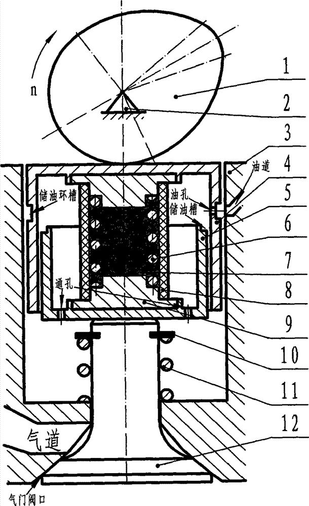
[0036] Such as figure 1 As shown, the technical solution structure of the present invention is made up of cam (1), frame (2), body (3), shear thickening tappet, valve spring seat (10), valve spring (11) and valve (12) . Among them: the shear thickening tappet consists of a large piston (4), a small piston (5), a piston return spring (6), a shear thickening liquid (7), a rubber sleeve (8) and an upper and lower base (9) composition.

[0037] Two, technical scheme system working process analysis of the present invention

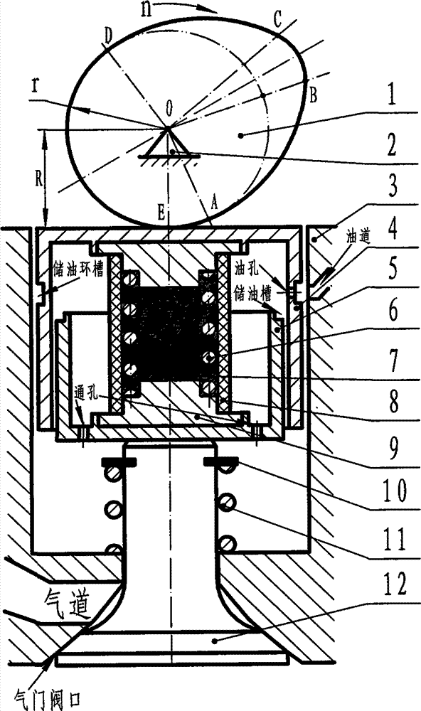
[0038] 1. If figure 2 As shown, the driving process of the cam base circle arc: as the cam (1) rotates around the rotation center O on the frame (2) at a speed n, the driving point E is within the base circle arc DA of the cam (1), along the The direction D→A is gradually changed to A, and the driving radius R is equal to the radius r of the base circle and remains unchanged. During this process, ① the shear thickening l...


PUM


Abstract

The invention discloses a piston engine valve timing and variable lift driving system. On the basis of the shear thickening fluid critical speed phase change characteristic and the cam speed change curve driving rule, the effective length of a shear thickening tappet changing in the same direction as change of rotation speed of a cam is adaptively obtained according to the change of the rotation speed of the cam (or the rotation speed of an engine), the opening advance angle, the lift and the closing delay angle of a valve are automatically adjusted, and thus the dynamic property, the strengthening degree, the low temperature startability, the low speed stability, the economical efficiency and the exhaust cleanliness of the engine are improved. According to the technical scheme, the system is free of electronic control, simple in mechanical structure, reliable in work, convenient to arrange, low in cost, easy to maintain, smooth in engine power output and capable of being widely applied to driving valves of various piston engines.

Description

technical field [0001] The invention relates to a driving technology of piston engine valves, in particular to the technical field of valve cam driving technology with variable opening advance angle, closing delay angle and lift of piston engine valves. Background technique [0002] At present, improving engine performance (including power, economy, reinforcement, exhaust cleanliness, low-speed stability and low-temperature startability, etc.) has become the most important goal pursued by engine technology research. The research results of piston engine structure optimization, combustion mechanism and experiments tell us: valve timing (corresponding to valve opening advance angle, closing delay angle and holding opening angle. They refer to: engine piston compression top dead center or exhaust The top dead center is the reference point, the crankshaft angle corresponding to the early opening time of the valve, the delayed closing time and the continuous opening time, the val...

Claims


Application Information

Patent Timeline
IPC IPC(8): F01L13/00
Inventor 范洪雷陈继梦范永建王福忠
Owner 范永建
Why Eureka
Try Eureka