
Transient grating effect based femtosecond laser pulse measuring device

A femtosecond laser and measurement device technology, applied in the field of femtosecond laser pulse measurement, can solve problems such as complex structure and short pulse measurement limitations, and achieve the effects of simple device structure, optimized output, and easy adjustment

Inactive Publication Date: 2014-10-29
SHANGHAI INST OF OPTICS & FINE MECHANICS CHINESE ACAD OF SCI
View PDF5 Cites 5 Cited by
  • Summary
  • Abstract
  • Description
  • Claims
  • Application Information

AI Technical Summary

Problems solved by technology

However, this method requires optical polarizing elements
Since the optical polarization element is only effective for a specific laser wavelength and has a certain spectral width, this limits the application of this method and instrument to a specific spectral range.
The dispersion of polarized optical components also limits the measurement of short pulses below 10fs
On a similar SRSI method, we have recently proposed two methods based on the self-diffraction effect [see literature 1: J.Liu, Y.L.Jiang, T.Kobayashi, R.X.Li, and Z.Z.Xu, “Self-referenced spectral interferometry based on self-diffraction effect, "J.Opt.Soc.Am.B29(1):29-34(2012); see patent: application number: 201210267065.3] and transient grating effect [see Document 2: J.Liu, F.J.Li , Y.L.Jiang, C.Li, Y.X.Leng, T.Kobayashi, R.X.Li, and Z.Z.Xu, “Transient-grating self-referenced spectral interferometry for infrared femtosecond pulse characterization,” Opt. Lett.37, 4829 (2012); see Patent: Application No.: 201210079324.X] femtosecond laser pulse measurement method, the two methods are not limited by dispersion, but the two methods are still relatively complicated in structure

Method used


Image

  • Transient grating effect based femtosecond laser pulse measuring device
  • Transient grating effect based femtosecond laser pulse measuring device
  • Transient grating effect based femtosecond laser pulse measuring device

Examples


Embodiment Construction

[0016] First, the interference spectrum signal is obtained by using the optical module based on the transient grating effect of the transparent medium and the spectrometer with high spectral precision.

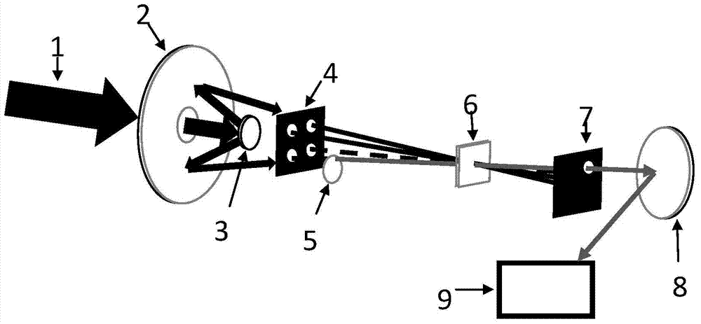
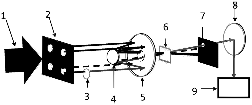
[0017] An embodiment device of the present invention such as figure 1 shown. The optical path mainly includes: 1 is the incident femtosecond laser beam; 2 is the first concave mirror; 3 is the convex mirror; 4 is the four-hole aperture plate; 5 is the variable neutral attenuation delay film; 6 is the third order Non-linear optical medium, used to generate transient grating effect; 7 is a small hole diaphragm plate, used to transmit signal light and block stray light; 8 is a second concave mirror; 9 is a spectrometer with high spectral accuracy, used to Measure laser spectra and interference spectra.

[0018] exist figure 1 In the shown optical path, the first concave reflector 2 and the convex reflector 3 form a focusing system; the four-aperture aperture plate 4 has four s...


PUM


Abstract

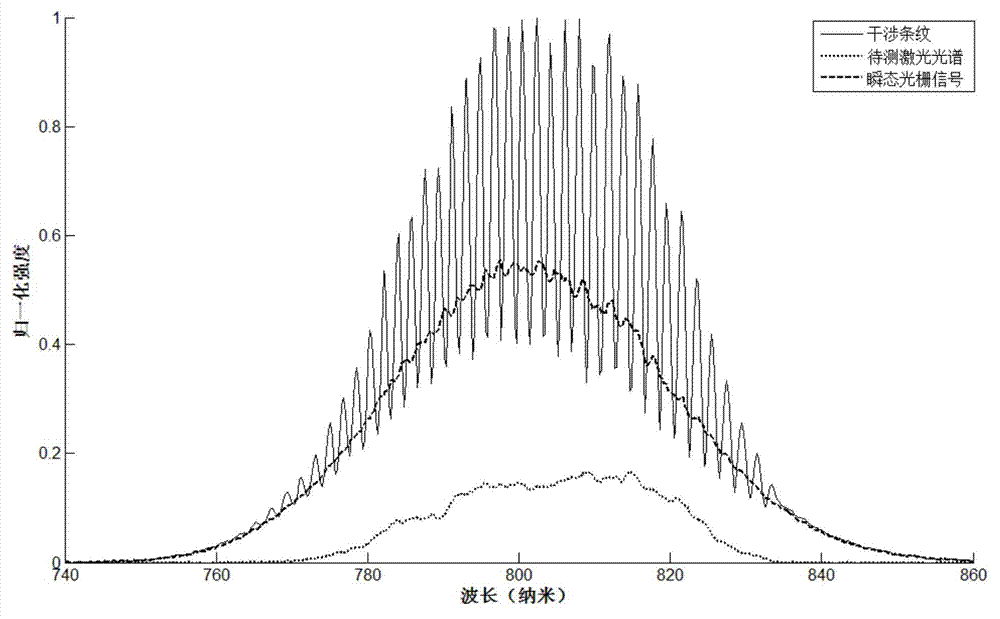
The invention discloses a transient grating effect based femtosecond laser pulse measuring device. The transient grating effect based femtosecond laser pulse measuring device is characterized in that incident to-be-measured laser pulses are divided into four beams, the three beams generate self-reference light through a transient grating effect of three-phase nonlinear mediums, the three beams and the fourth beam of to-be-measured light are superposed in space and focused into a spectrometer to enable self-reference interference spectrums to be obtained, femtosecond laser pulse shapes, laser spectrums and spectrum phases are calculated through a self-reference spectrum coherent method due to measurement of interference spectrums. The transient grating effect based femtosecond laser pulse measuring device has the advantages of being compact and stable in structure and miniaturized in integrity due to the fact that a focusing system is formed by a concave mirror and a convex mirror or a plane mirror and the concave mirror and not needing an optical polarization element and being applied to femtosecond laser optical systems with the spectrum and the pulse width to be respectively from 200 to 3000nm and 10 to 300fs.

Description

technical field [0001] The invention relates to femtosecond laser pulse measurement, in particular to a femtosecond laser pulse measurement device based on transient grating effect. Background technique [0002] Femtosecond laser has been developed extremely rapidly due to its needs in scientific research, biology, medical treatment, processing, communication, national defense and other fields. As the important optical parameters of femtosecond laser pulses, the shape and pulse width of femtosecond laser pulses are very necessary for their measurement or real-time monitoring. Therefore, finding a simple, convenient, fast and effective method and device for measurement and real-time monitoring plays a very important role in promoting the development of femtosecond laser itself and expanding its application in various fields. [0003] Currently, the most widely used femtosecond laser pulse measurement techniques are: 1. Frequency Resolved Optical Gating (FROG); 2. Spectral Ph...

Claims


Application Information

Patent Timeline
Patent Type & Authority Applications(China)
IPC IPC(8): G01J9/02
Inventor 刘军申雄王鹏李方家
Owner SHANGHAI INST OF OPTICS & FINE MECHANICS CHINESE ACAD OF SCI
Learn More