
Method for computing actual focal length of variable-focal-length lens based on liquid crystal spatial light modulator

A technology of spatial light modulator and calculation method, which is applied in the field of optics, can solve the problems of deviation of the focus position of the beam from the focus position, unable to obtain the focus position, deviation of phase modulation, etc., and achieves accurate calculation, improved imaging quality and wide adaptability. Effect

Active Publication Date: 2014-10-29
SHENZHEN UNIV
View PDF3 Cites 11 Cited by
  • Summary
  • Abstract
  • Description
  • Claims
  • Application Information

AI Technical Summary

Problems solved by technology

[0004] Due to the influence of the phase modulation depth of the liquid crystal spatial light modulator, the nonlinear mapping relationship between the actual phase modulation degree and the lens phase grayscale image, the actual phase grayscale image loaded into the liquid crystal spatial light modulator The phase modulation of the beam deviates from the ideal situation, causing the actual focus position of the beam to deviate from the focus position of the theoretical design
However, the current liquid crystal spatial light modulator does not consider this situation, and the actual phase modulation is completely consistent with the ideal situation by default, and the accurate focus position cannot be obtained, and the calculation is not accurate enough

Method used


Image

  • Method for computing actual focal length of variable-focal-length lens based on liquid crystal spatial light modulator
  • Method for computing actual focal length of variable-focal-length lens based on liquid crystal spatial light modulator
  • Method for computing actual focal length of variable-focal-length lens based on liquid crystal spatial light modulator

Examples


Embodiment 1

[0061] This embodiment describes the relevant theories and principles of the method for calculating the actual focal length of a variable-focus lens based on a liquid crystal spatial light modulator in the present invention.

[0062] Ideally, when incident light waves pass through lenses with different thicknesses, different phase delays will occur, so the lens can be regarded as a phase-type diffraction screen.

[0063] Under the condition of paraxial approximation, according to the scalar diffraction theory, the phase distribution function of the lens is:

[0064]

[0065] The present invention introduces pupil function P (x, y) to represent the finite aperture of lens, and the expression of pupil function P (x, y) is:

[0066]

[0067] Therefore, the complex amplitude transmittance function t(x, y) of the lens can be expressed as:

[0068]

[0069] Among them, i represents the imaginary unit.

[0070] For a given wavelength of incident light and the focal length ...

Embodiment 2

[0078] In this embodiment, a transmissive liquid crystal spatial light modulator is taken as an example to illustrate the calculation process of the actual focal length of the variable focus lens.

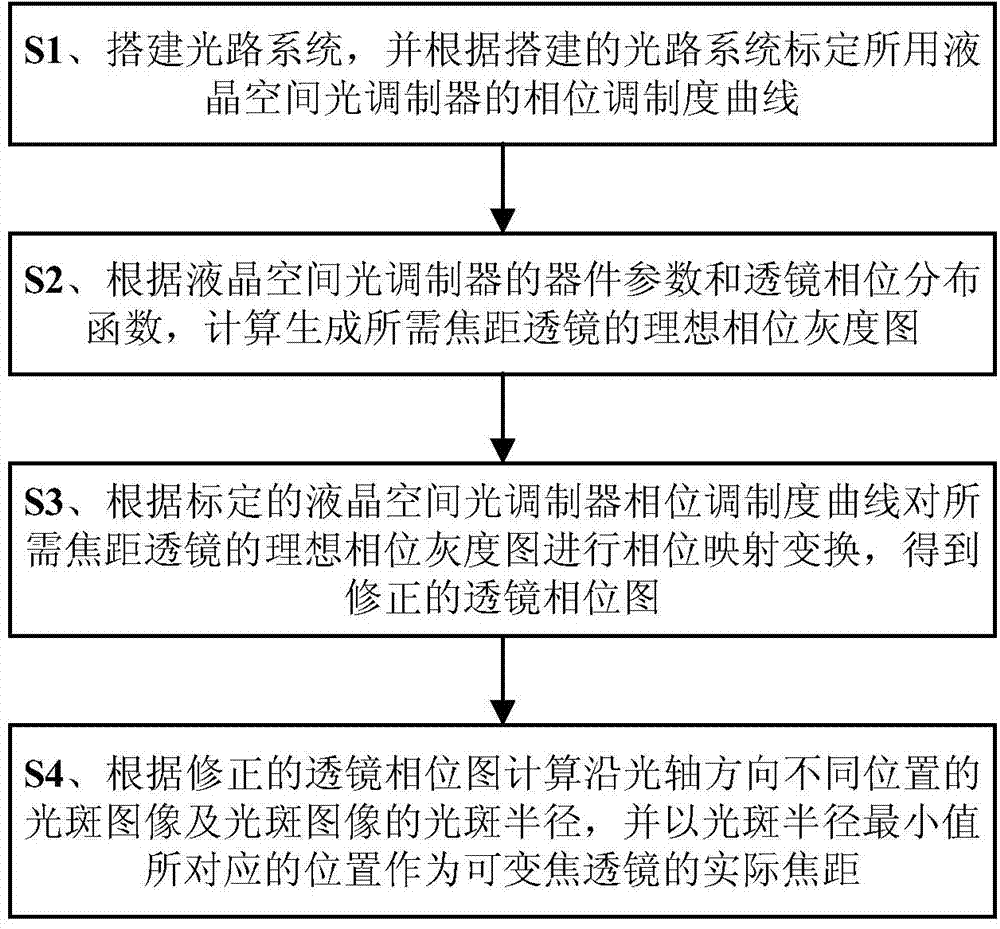
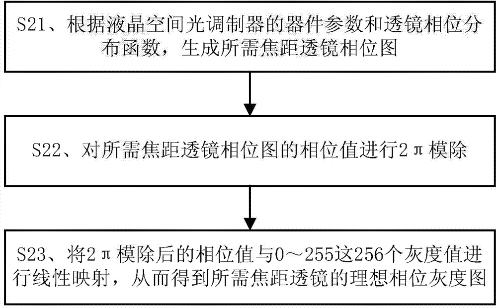
[0079] The liquid crystal spatial light modulator has phase modulation characteristics. After loading the grayscale image, it will control the voltage value at both ends of the liquid crystal panel according to the grayscale value of the grayscale image, so that the refractive index of the liquid crystal molecules will change, thereby realizing the phase adjustment of the incident light wave. modulation. According to the lens phase distribution function, the lens phase map of the required focal length is calculated and generated, and then the value of the phase distribution function is divided by 2π modulo and linearly mapped with 256 gray values ​​to obtain the ideal lens phase gray map, and finally the ideal lens phase The grayscale image can be loaded into the liquid crystal spa...

Embodiment 3

[0090] use as Figure 8 The optical path system shown realizes the focal length measurement of the zoom lens based on the transmissive liquid crystal spatial light modulator to verify the method of the present invention. Such as Figure 8 As shown, the laser beam emitted by the laser 101 passes through the continuously adjustable attenuator 102, the beam expander and collimator 103, the diaphragm 104, the polarizer 105, the transmissive liquid crystal spatial light modulator 109 and the analyzer 111 in turn, surrounding the light The axis rotates the polarizer 105 and the analyzer 111 , and the light field distribution is collected by the camera 112 , and the computer 113 controls the transmissive liquid crystal spatial light modulator 109 and the camera 112 during this process. Set the angle between the light transmission axis of the polarizer 105 and the light transmission axis of the analyzer 111 as the angle determined when the phase modulation degree is calibrated, so th...


PUM


Abstract

The invention discloses a method for computing an actual focal length of a variable-focal-length lens based on a liquid crystal spatial light modulator. The method includes: constructing a light path system and calibrating a phase modulation degree curve of the liquid crystal spatial light modulator according to the constructed light path system; computing an ideal phase grey-scale image for generating the lens with a required focal length according to device parameters of the liquid crystal spatial light modulator and a lens phase distribution function; subjecting the ideal phase grey-scale image of the lens with the required focal length to phase mapping transformation according to the calibrated phase modulation degree curve of the liquid crystal spatial light modulator so as to obtain a modified lens phase image; computing light spot images at different positions along the light axis direction and spot radiuses of the light spot images according to the modified lens phase image, and taking the position corresponding to a minimum spot radius value as the actual focal length of the variable-focal-length lens. The method has the advantages that the actual focal length of the variable-focal-length lens can be obtained quickly by computation based on the liquid crystal spatial light modulator, and the method is accurate in computing and wide in applicability and can be widely applied to the technical field of photology.

Description

technical field [0001] The invention relates to the field of optical technology, in particular to a method for calculating the actual focal length of a variable focus lens based on a liquid crystal spatial light modulator. Background technique [0002] With the continuous development of science and technology, the design theory and production technology of optical zoom system are becoming more and more perfect. Optical zoom systems are widely used in microscopes, telescopes, projectors, cameras and other instruments and equipment. In traditional optical zoom systems, the focal length of the entire objective lens can be changed by changing the relative position of the lens groups to realize the zoom function of the system. Usually, this optical zoom system adopts mechanical components such as a cam mechanism and a stepping motor for displacement control, and the imaging quality, response speed and zoom range of the system are greatly limited. Therefore, the industry needs a...

Claims


Application Information

Patent Timeline
Patent Type & Authority Applications(China)
IPC IPC(8): G02B3/12G02F1/13
Inventor 田劲东张磊李东
Owner SHENZHEN UNIV
Learn More