Process pressure control in nylon synthesis
A gaseous mixture, liquid technology, applied in the field of continuous polyamide synthesis system, can solve the problems of expensive, expensive production cost brokers, waste generation and so on
- Summary
- Abstract
- Description
- Claims
- Application Information
AI Technical Summary
Problems solved by technology
Method used
Image

Examples
Embodiment
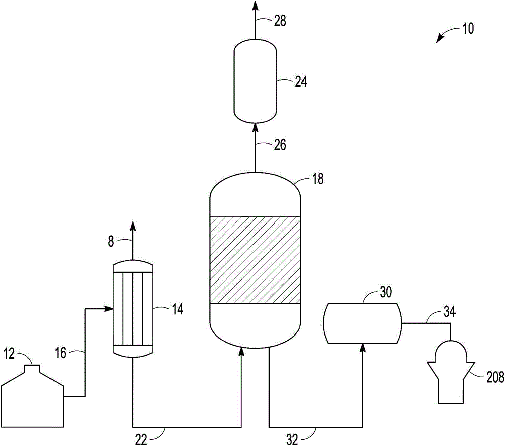
[0079] continuous polymerization process. In the examples given in this section the following methods were carried out. In the continuous nylon 6,6 manufacturing process, adipic acid and hexamethylenediamine are mixed in water in an approximately equimolar ratio in a salt bath to form an aqueous nylon 6,6 salt containing nylon 6,6 salt having about 50% by weight water. mixture. The aqueous salt was transferred to the evaporator at about 105 L / min. The evaporator heats the brine solution to about 125-135°C (130°C) and removes water from the heated brine solution such that the water concentration reaches about 30% by weight. The evaporated salt mixture was transferred to the reactor at about 75 L / min. The reactor brings the temperature of the evaporated salt mixture to about 218-250°C (235°C), allowing the reactor to further remove water from the heated evaporated salt mixture, bringing the water concentration to about 10% by weight, and causing further polymerization of the...
Embodiment 1c
[0087] Example 1c: Finisher with atmospheric leg recirculation and liquid ring vacuum pump.
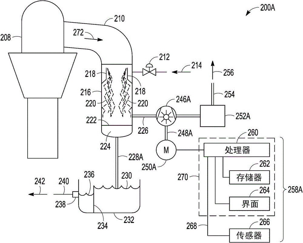
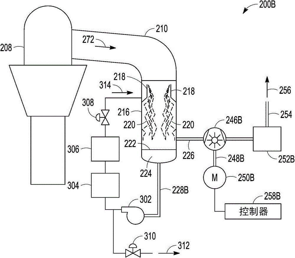
[0088] A continuous polymerization process is carried out. The exhaust from finisher 208 is routed to exhaust condenser 216 . Vent condenser 216 includes a liquid reservoir 224 fitted with a discharge line. An exhaust line, sometimes called the atmospheric leg, connects to a low point in the reservoir 224 . A pump connected to the atmospheric leg transfers the liquid from the reservoir 224 to the filter and cooler 306 and thereafter returns the fluid to the weir 218 and ejector arranged above the exhaust condenser 216 .
[0089] Vacuum line 420 connects to exhaust condenser 216 at a point above liquid reservoir 224 . Vacuum line 420 is connected to 304 austenitic steel liquid ring vacuum pump 246C which pumps out 1000m 3 / h. The LRVP 246C is vented to a scrubber and thereafter vented to atmosphere. The polymer mixture leaving LRVP246C contained about 0.5 ppm iron, which reduced...
Embodiment 2a
[0090] Example 2a: Comparative example. Finisher with atmospheric leg discharge and mechanical vane pump.
[0091] A continuous polymerization process is carried out. The exhaust from the finisher is sent to an exhaust condenser. The vent condenser includes a liquid reservoir fitted with a discharge line. The discharge line, sometimes called the atmospheric leg, connects to a low point in the reservoir. The liquid in the atmospheric leg is set to the collection tank route. A collection tank, sometimes called a thermal well, consists of a weir and a discharge. Collection tank discharges to sanitary sewer. A separate water supply line is connected to a weir and ejector arrangement located above the exhaust condenser.
[0092] The vacuum line was connected to the exhaust condenser at a point above the liquid reservoir. The vacuum line is connected to a 304 austenitic steel mechanical vane pump which pumps out 1000m 3 / h. The vacuum pump discharges to the scrubber and the...
PUM
 Abstract
Description
Claims
Application Information