Sealing component and container for power storage device

A sealing part and sealing technology, applied in electrochemical generators, battery pack parts, batteries, etc., can solve the problems of small volume ratio, low production efficiency, complex structure, etc., and achieve simple manufacturing equipment, efficient manufacturing, and simple structure. Effect

Inactive Publication Date: 2014-11-05
FUJIMORI KOGYO CO LTD
View PDF2 Cites 3 Cited by
  • Summary
  • Abstract
  • Description
  • Claims
  • Application Information

AI Technical Summary

Problems solved by technology

[0007] However, the battery cover is very heavy because the cover material and the flange are formed from metal.
Also, due

Method used


Image

  • Sealing component and container for power storage device
  • Sealing component and container for power storage device
  • Sealing component and container for power storage device

Examples


Embodiment 1

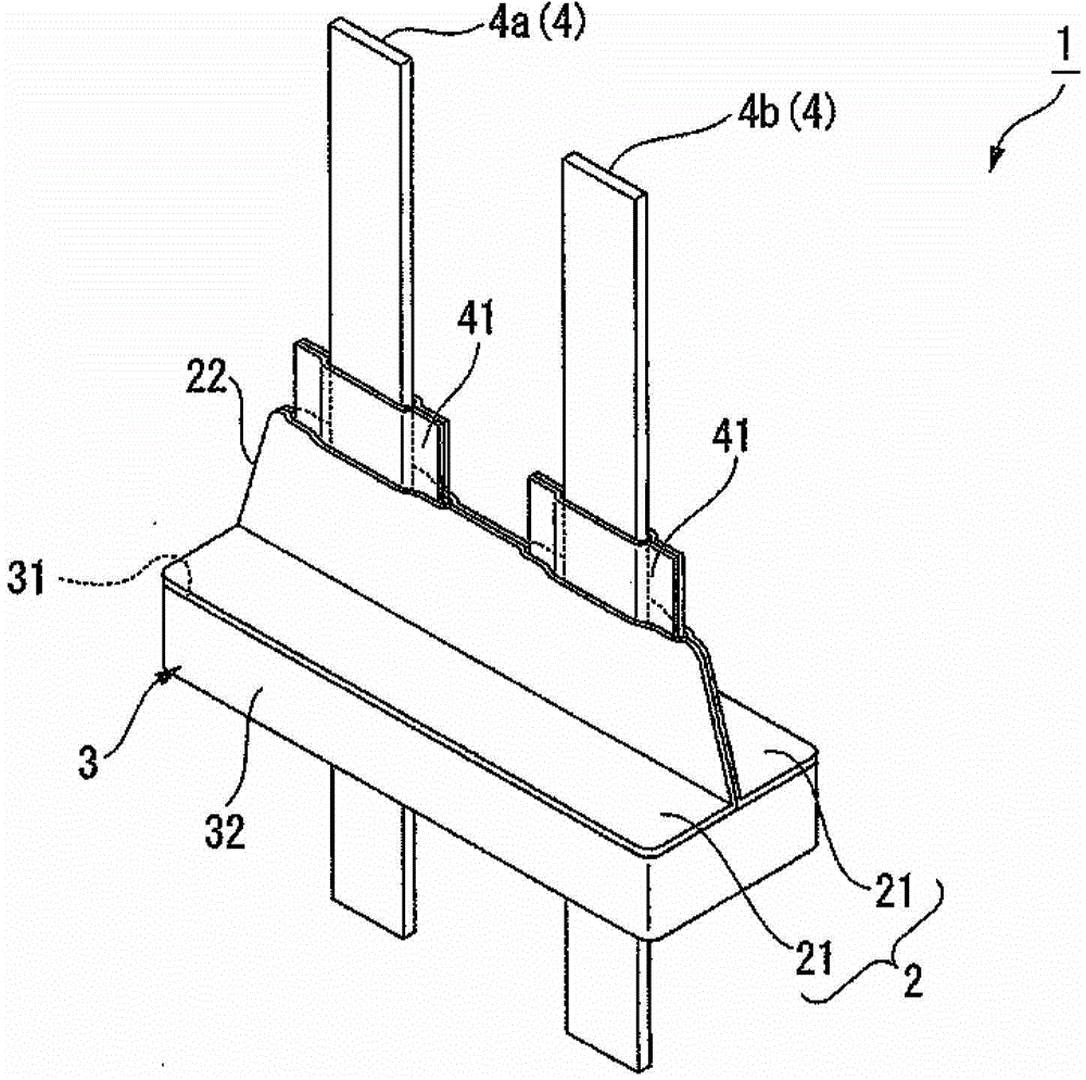
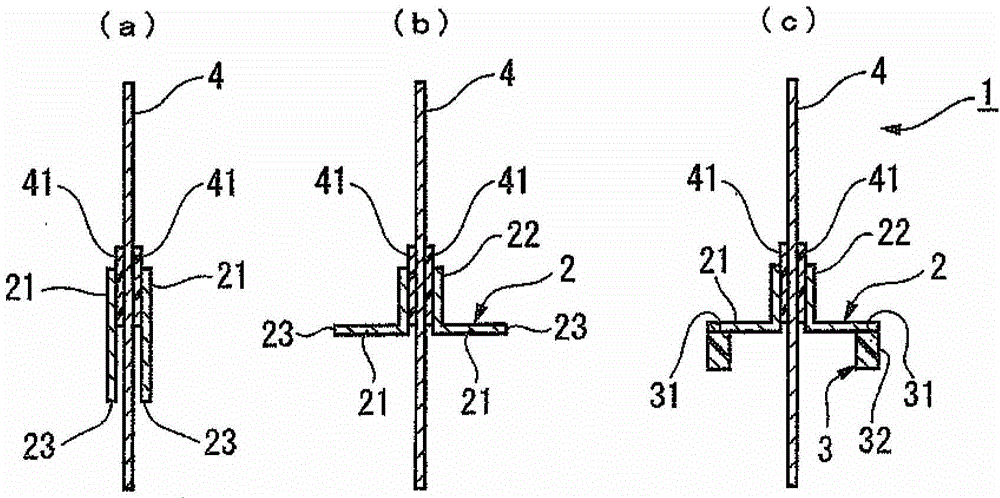
[0185] Example 1 is with Figure 1 ~ Figure 3 This is an example related to the first aspect shown.

[0186]

[0187] As the electrode terminal 4, a positive electrode terminal 4a made of aluminum foil having a width of 5 mm, a length of 50 mm, and a thickness of 0.2 mm and a negative electrode terminal 4b made of nickel-plated copper foil of the same size were used. As the insulating layer 41 , four insulating films composed of maleic anhydride grafted modified PP films with a width of 10 mm, a length of 12 mm and a thickness of 0.05 mm are used.

[0188] The electrode terminal 4a is sandwiched between two insulating films corresponding to the center line of the width and length, and a pair of hot plates are used to weld the insulating films as a whole to produce the electrode terminal 4a with an insulating layer 41 . The electrode terminal 4b with the insulating layer 41 is produced similarly.

[0189] For the electrode terminals 4a, 4b with the insulating layer 41, the ...

Embodiment 2

[0205] Example 2 is with Figure 4 ~ Figure 6 An example related to the second aspect shown. Example 2 is the same as Example 1 except that the configuration of the sealing wall 2 and the fixing configuration of the electrode terminals 4 are different. Hereinafter, only the different points will be described.

[0206]

[0207] The metal foil laminate produced in Example 1 was cut into a rectangle having a width of 50 mm and a length of 20 mm to produce a sealing wall 2 .

[0208]

[0209] The long sides of the produced sealing wall 2 and the long sides of the frame body 3 are aligned and overlapped. Between the sealing wall 2 and the frame body 3 , the electrode terminals 4 a and 4 b with insulating layers 41 used in Example 1 are arranged perpendicular to the long sides of the frame body 3 . When disposing, the insulation layers 41, 41 of the electrode terminals 4a, 4b are arranged in parallel with a distance of 8 mm, respectively located at positions 6 mm away from bo...

Embodiment 3

[0214] Example 3 is with Figure 7 ~ Figure 9 An example related to the third aspect shown. Example 3 is the same as Example 1 except that the form of the sealing wall 2 and the form of fixing the electrode terminal 4 are different. Hereinafter, only the different points will be described.

[0215]

[0216] The metal foil laminate produced in Example 1 was cut into a rectangle with a width of 50 mm and a length of 25 mm to produce a sealing wall 2 .

[0217]

[0218] The electrode terminal 4a used in Example 1 was sandwiched between the two insulating films used in Example 1 in the same manner as in Example 1. One end in the longitudinal direction of the two insulating films sandwiching the electrode terminal 4a was welded with a hot plate in a width of 5 mm across the entire width direction of the insulating films. The insulating films are welded to each other at both ends in the width direction of the insulating films where the electrode terminals 4a are not present a...


PUM

PropertyMeasurementUnit
Thicknessaaaaaaaaaa

Abstract

The invention provides a sealing component and a container for a power storage device. The container for the power storage device is welded with the sealing component. The sealing component is simple in structure and high in production efficiency, and has high gas barrier properties which cannot make gases, such as steam and oxygen gas, transmit easily. The container for a power storage device has light weight and high floor area ratio, and has small moisture immersed from connection parts of the sealing component and liquid components evaporated from a content article. The sealing component (1) is welded on an opening inner surface of a cylinder (51) having a welding property so as to seal the opening. A sealing wall (2) consists of a metallic foil laminated body having a metallic foil and a welding layer is welded on the top surface of a frame made of a resin. Electrode terminals (4,4) are fixed to the sealing wall (2) airtightly.

Description

technical field [0001] The present invention relates to a sealing member used in a container for an electrical storage device for accommodating an electrical storage element, and a container for an electrical storage device in which the sealing member is welded. Background technique [0002] Conventionally, metal containers having excellent water vapor permeation resistance have been widely used as containers for electric storage devices that house electric storage elements of electric storage devices such as lithium-ion rechargeable batteries and capacitors. However, metal containers are heavy and bulky, and the packaging process is complicated, so productivity is poor. In particular, the welding of the container main body and the lid body requires a lot of labor, and there is a problem in terms of productivity. Furthermore, since the number of rechargeable batteries for electric vehicles is mounted in the vehicle, it is desirable that the container is light and has a larg...

Claims


Application Information

Patent Timeline
IPC IPC(8): H01M2/02H01M2/06H01M2/04H01M2/08
CPCH01M10/0525H01M50/10H01M50/147H01M50/183Y02E60/10H01M2220/30H01M50/172H01M50/188H01M50/164H01M50/16H01M50/157H01M50/557H01M50/15H01M50/103H01M50/141
Inventor 饭塚宏和佐藤考勇中村勉
Owner FUJIMORI KOGYO CO LTD
Why Eureka
Try Eureka