Sludge treatment equipment

A sludge treatment and equipment technology, applied in the fields of sludge treatment, water/sludge/sewage treatment, dewatering/drying/concentrated sludge treatment, etc., can solve the problem of damage, freezing of sewage, and inability to store water-containing sludge evenly and other problems, to prevent damage and reduce the burden

Active Publication Date: 2015-12-02
MITSUBISHI MATERIALS CORP
View PDF9 Cites 0 Cited by
  • Summary
  • Abstract
  • Description
  • Claims
  • Application Information

AI Technical Summary

Problems solved by technology

[0007] However, when the water-containing sludge is put into the sludge bin by a truck and stored, if Figure 5 As shown, since it is always input from the input port 9 on one side of the sludge bin 2, the water-containing sludge 5 cannot be evenly stored in the sludge bin 2, resulting in accumulation on the side.
At this time, there is the following problem in the conventional sludge treatment equipment: since the spraying part 7a of the sewage return pipe 7 that returns the sewage 6 from the sewage recovery tank to the sludge storage tank 2 is arranged on the side of the sludge storage tank The other side opposite to the side of the input port 9 of the water-containing sludge 5 of the truck 8, so the sewage 6 is not mixed with the water-containing sludge 5, causing only the sewage 6 to accumulate on the other side, and the water-containing sludge 5 When put into the rotary kiln, the water content of the water-containing sludge 5 deviates, and when the water content increases, the burden on the rotary kiln increases
[0008] And, when used in winter or in cold regions, there is also the following problem: the sewage 6 in the sewage recovery tank is frozen, and the sewage return pump and the sewage return pump that returns the sewage 6 to the sludge bin 2 are frozen. The sewage return pipe, etc. may be damaged due to the freezing of the sewage
However, since the truck 8 that has transported the water-containing sludge 5 from the sewage treatment plant puts the water-containing sludge 5 into the sludge bin 2, and then directly leaves the sludge treatment facility, there is a cargo remaining on the truck 8. If the water-containing sludge 5 on the platform 8a is dried and sticks to the cargo platform 8a, or when the cargo platform 8a is cleaned in other places, the sewage treatment needs to be performed separately.

Method used


Image

  • Sludge treatment equipment
  • Sludge treatment equipment
  • Sludge treatment equipment

Examples


Embodiment Construction

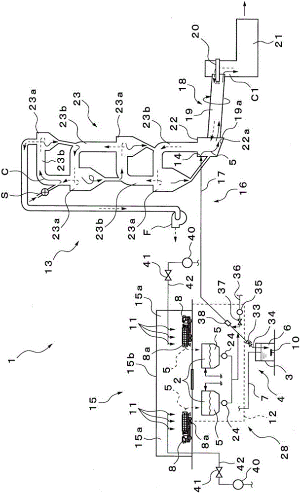
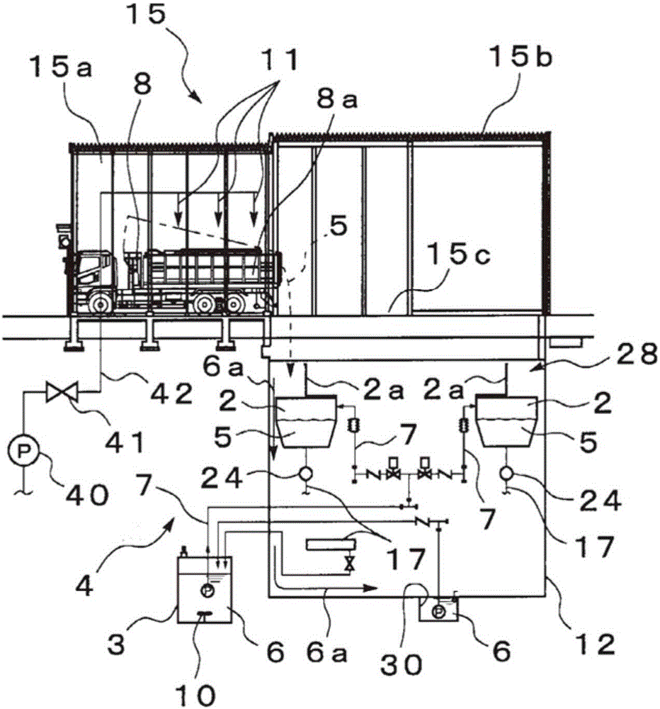
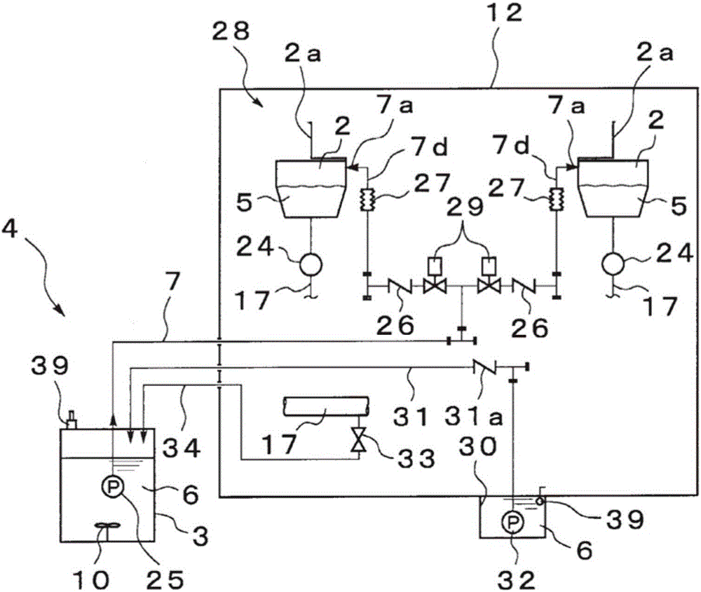
[0030] Such as figure 1 As shown, a sludge treatment facility 1 according to an embodiment of the present invention is schematically configured to include a cement manufacturing facility (cement manufacturing process) 13 having a dry-process rotary kiln 18 and a preheater for preheating cement raw material C 23; sludge receiving equipment 15, which receives the truck 8 that carries the water-containing sludge 5 from the sewage treatment plant; spraying device 11, which is equipped in the sludge receiving equipment 15; sludge bin accommodation equipment 28, which has sludge silo 2 and sewage recovery tank 3, storing water-containing sludge 5 in the sludge silo 2, and the sewage recovery tank 3 recovers and stores the sludge when cleaning the sludge silo 2 or the piping connected to the sludge silo 2 Sewage 6 ; and a sludge input mechanism 16 that injects the hydrous sludge 5 from the kiln tail 19 a side of the dry rotary kiln 18 through the sludge introduction pipe 17 .

[00...


PUM


Abstract

Provided is sludge treatment facility that can spray contaminated water evenly in water-containing sludge that has been deposited in a sludge hopper. This sludge treatment facility (1) is provided with a contaminated water recovery mechanism (4) which comprises: a contaminated water recovery tank (3) for recovering contaminated water (6) resulting from cleaning either a sludge hopper (2) that stores water-containing sludge (5) transported from a sewage treatment plant by truck (8) or pipes in the sludge treatment facility (1); and a contaminated water return pipe (7) that transports the water from the contaminated water recovery tank (3) to the sludge hopper (2). The water-containing sludge (5) that is stored in the sludge hopper (2) is treated by a cement manufacturing process (13). A water spraying unit (7a) on the sludge hopper (2) side of the contaminated water return pipe (7) is disposed above the dropping position for the water-containing sludge (5) into the sludge hopper (2) from the truck (8) such that the contaminated water (6) is sprayed onto the peak (5a) of the water-containing sludge (5) that has collected within the sludge hopper (2).

Description

technical field [0001] The present invention relates to a sludge treatment equipment for putting sewage sludge discharged from a sewage treatment plant into a cement kiln to realize cement raw materials. [0002] This application claims priority based on Japanese application No. 2012-042786 for which it applied in Japan on February 29, 2012, and uses the content here. Background technique [0003] In recent years, as sludge treatment of sewage sludge discharged from a sewage treatment plant, a technique of directly injecting sewage sludge cake into a cement clinker kiln to convert cement into a raw material has been proposed and put into practical use. This technology uses trucks (trucks) to move sewage dewatered sludge (water-containing sludge) that has been treated to a moisture content of about 80%, and directly puts it into a cement kiln as a cement clinker firing furnace with a pressure pump, and heats it at high temperature. Thereby, moisture and combustible component...

Claims


Application Information

Patent Timeline
Patent Type & Authority Patents(China)
IPC IPC(8): C02F11/00C04B7/38C02F11/12
CPCC02F11/06C02F11/12C04B7/24Y02P40/145Y02P40/10
Inventor 堀池超辻和秀
Owner MITSUBISHI MATERIALS CORP
Why Eureka
Try Eureka