A photocatalytic structure for splitting water and its manufacturing method

A manufacturing method, a technology of photolysis of water, which is applied in the field of photocatalysis, can solve the problems of not greatly improving, achieve low cost, simple structure and process, and solve the effect of low efficiency of photolysis of water

Inactive Publication Date: 2016-04-13
SUZHOU UNIV
View PDF3 Cites 0 Cited by
  • Summary
  • Abstract
  • Description
  • Claims
  • Application Information

AI Technical Summary

Problems solved by technology

[0004] However, the α-Fe 2 o 3 The efficiency of photolysis of water and improve the pure α-Fe 2 o 3 The photo-water splitting efficiency is beneficial to improve the α-Fe-based 2 o 3 The photo-water splitting efficiency of composite photocatalysts, but currently can improve the pure α-Fe 2 o 3 There are few methods for photocatalytic water splitting efficiency; in addition, most of the existing photocatalytic structures for photocatalytic water splitting directly use the purchased transparent conductive glass as the substrate, therefore, the amount of heteroelement doping cannot be controlled, and the Catalytic Efficiency to Improve Photowater Splitting Efficiency of Photocatalytic Structures

Method used


Image

  • A photocatalytic structure for splitting water and its manufacturing method
  • A photocatalytic structure for splitting water and its manufacturing method
  • A photocatalytic structure for splitting water and its manufacturing method

Examples


Embodiment 1

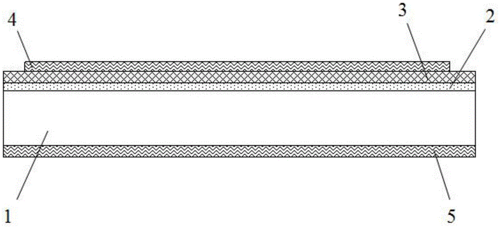
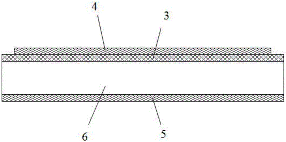
[0038] Please refer to figure 1 , figure 1 It is a schematic diagram of the structure of the photocatalytic water splitting of the present invention, such as figure 1 As shown, the photocatalytic structure of the present invention includes: a glass substrate 1; a conductive layer 2 located on the upper surface of the glass substrate 1 to form a conductive substrate, and the conductive layer 2 is fluorine-doped tin oxide or aluminum-doped oxide Zinc conductive film, the fluorine-doped tin oxide is 5% by mass or the aluminum-doped zinc oxide is 8% by mass, and the fluorine-doped tin oxide or aluminum-doped oxide is The thickness of the zinc conductive film is 50nm; the photocatalyst layer 3 is located on the upper surface of the conductive layer 2, and the photocatalyst layer 3 is pure α-Fe 2 o 3, whose thickness is 200nm; and a cover layer, which includes an upper cover layer 4 and a lower cover layer 5, the upper cover layer 4 is located on the upper surface of the photocat...

Embodiment 2

[0051] Please refer to figure 1 , figure 1 It is a schematic diagram of the structure of the photocatalytic water splitting of the present invention, such as figure 1 As shown, the photocatalytic structure of the present invention includes: a glass substrate 1; a conductive layer 2 located on the upper surface of the glass substrate 1 to form a conductive substrate, and the conductive layer 2 is fluorine-doped tin oxide or aluminum-doped oxide Zinc conductive film, the fluorine-doped tin oxide has a mass percentage of 7% or the aluminum-doped zinc oxide has a mass percentage of 9%, and the fluorine-doped tin oxide or aluminum-doped oxide The thickness of the zinc conductive film is 120nm; the photocatalyst layer 3 is located on the upper surface of the conductive layer 2, and the photocatalyst layer 3 is pure α-Fe 2 o 3 , whose thickness is 300nm; and a cover layer, which includes an upper cover layer 4 and a lower cover layer 5, the upper cover layer 4 is located on the up...

Embodiment 3

[0064] Please refer to figure 1 , figure 1 It is a schematic diagram of the structure of the photocatalytic water splitting of the present invention, such as figure 1 As shown, the photocatalytic structure of the present invention includes: a glass substrate 1; a conductive layer 2 located on the upper surface of the glass substrate 1 to form a conductive substrate, and the conductive layer 2 is fluorine-doped tin oxide or aluminum-doped oxide Zinc conductive film, the fluorine-doped tin oxide has a mass percentage of 8% by mass or the aluminum-doped zinc oxide has an aluminum-doped mass percentage of 10%, and the fluorine-doped tin oxide or aluminum-doped oxide The thickness of the zinc conductive film is 200nm; the photocatalyst layer 3 is located on the upper surface of the conductive layer 2, and the photocatalyst layer 3 is pure α-Fe 2 o 3 , whose thickness is 400nm; and a covering layer, which includes an upper covering layer 4 and a lower covering layer 5, the upper ...


PUM

PropertyMeasurementUnit
thicknessaaaaaaaaaa
thicknessaaaaaaaaaa
thicknessaaaaaaaaaa

Abstract

The invention relates to the technical field of photocatalysis, and discloses a photocatalytic water splitting catalyzing structure. The photocatalytic water splitting catalyzing structure comprises a substrate, a conductive layer, a photocatalyst layer and covering layers, wherein the conductive layer is positioned on the upper surface of the substrate so as to form a conductive substrate; the photocatalyst layer is positioned on the upper surface of the conductive layer; the covering layers comprise an upper covering layer and a lower covering layer, the upper covering layer is positioned on the upper surface of the photocatalyst layer and covers part of the photocatalyst layer, and the lower covering layer is positioned on the lower surface of the substrate, and covers all the lower surface of the substrate. The invention also discloses a method for preparing the photocatalytic water splitting catalyzing structure. According to the invention, a high-temperature resisting conductive film is prepared on the substrate and can be flexibly applied to substrates of different types; the quantity of elements doped in the transparent conductive film can be accurately controlled; a photocatalyst precursor is synthesized by a hydrothermal method, the cost is relatively low, the operability is high, the pH value is adjusted by hydrochloric acid with proper concentration, and the technical problem that pure alpha-Fe2O3 is low in photocatalytic water splitting efficiency at present is solved.

Description

technical field [0001] The invention relates to the technical field of photocatalysis, in particular to a nanomaterial-based photocatalytic structure for splitting water and a manufacturing method thereof. Background technique [0002] In the face of increasingly severe energy and environmental crises, it is imperative for human beings to find new renewable clean energy sources. In recent years, hydrogen energy, as a rising star, has received widespread attention due to its unique advantages. The photo-splitting water hydrogen production system uses solar energy to decompose combined water to generate free hydrogen, thereby storing unstable solar energy in the form of hydrogen energy, which not only improves the utilization rate of solar energy and water energy, but also produces clean and sustainable energy. Renewable hydrogen energy resources. [0003] Theoretical predictions indicate that α-iron oxide (α-Fe 2 o 3 ) has a photo-water splitting efficiency as high as 16.8...

Claims


Application Information

Patent Timeline
Patent Type & Authority Patents(China)
IPC IPC(8): B01J23/745B01J23/89B01J23/80B01J23/835C01B3/04
CPCY02E60/36
Inventor 钟俊
Owner SUZHOU UNIV
Why Eureka
Try Eureka