Power transmission line covered ice monitoring device based on rotation reference conductor

A transmission line and monitoring device technology, applied in the field of electric power equipment, can solve the problems of reducing the timeliness and accuracy of monitoring results, demanding camera installation angles, and increasing the labor intensity of patrol personnel, so as to ensure the stability and reliability of power supply, Improved timeliness and simple structure

Active Publication Date: 2014-11-19
CHONGQING UNIV +1
4 Cites 5 Cited by

AI-Extracted Technical Summary

Problems solved by technology

The video monitoring method is to obtain the icing image of the transmission line through the camera and process it, and extract the boundary contour to estimate the ice thickness on the transmission line. However, there are many difficulties in the actual application of the video method. The quality of the monitoring system used in the video monitoring method The size of the camera is large, the installation angle of the camera is demanding, and it is easy to cause distortion of the monitoring image. Especially when the icing is serious, the camera is covered by ice and snow and it is difficult to capture the icing of the transmission line. As a ...

Method used

In the present embodiment, described reference conductor 1 is tubular structure, and the outer diameter of described reference conductor 1 is identical with the wire diameter of transmission line and the material of reference conductor 1 is identical or similar to the material of transmission line, by above-mentioned The reference conductor, in the process of monitoring ice, can ensure the consistency and synchronization of the reference conductor and the transmission line, so that the accuracy of the monitoring results can be guaranteed to the greatest extent, and through the reference conductor of the tubular structure, it can benefit the reference conductor The layout of the ice-melting unit simplifies the layout structure and facilitates manufacturing and installation.
In the present embodiment, described two conductor mounting bases 2 are all provided with mounting holes 10, wherein the mounting hole 10 of one conductor mounting base 2 is a blind hole, and the mounting hole 10 of another mounting base 2 is a through hole, The two ends of the copper pipe 6 are respectively fixedly arranged in the installation holes 10 and the insulated heating wire 7 passes through the installation holes 10 which are through holes. Through this structure, on the one hand, it is beneficial to effectively fix customs clearance, on the other hand It facilitates the electr...

Abstract

The invention provides a power transmission line covered ice monitoring device based on a rotation reference conductor. The power transmission line covered ice monitoring device at least comprises the reference conductor, a hanging support and a tension sensor. The reference conductor can be rotationally connected with the tension sensor. The tension sensor is fixedly connected with the hanging support. An ice melting unit is arranged in the reference conductor. The reference conductor rotates under the actions of wind force and covered ice gravity so that uniform cylindrical covered ice can be formed on the surface of the reference conductor; the tension sensor is utilized for monitoring the weight of the covered ice to carry out simulated monitoring on the covered ice of a power transmission line, the covered ice of the power transmission line can be effectively monitored, the effect of the environment on the monitoring result is effectively avoided, and the covered ice monitoring accuracy can be greatly improved.

Application Domain

Technology Topic

Image

  • Power transmission line covered ice monitoring device based on rotation reference conductor
  • Power transmission line covered ice monitoring device based on rotation reference conductor

Examples

  • Experimental program(1)

Example Embodiment

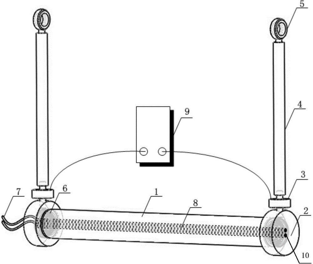
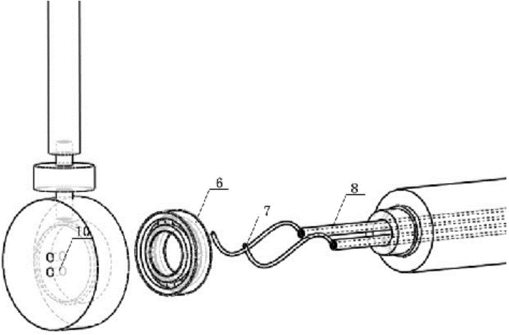
[0019] figure 1 Is a schematic diagram of the structure of the present invention, figure 2 This is a partial exploded view of the present invention. As shown in the figure, a transmission line ice monitoring device based on a rotating reference conductor provided by the present invention at least includes a reference conductor 1, a suspension bracket, and a tension sensor 3. The reference conductor 1 is It is connected to the tension sensor 3 in a rotatable manner, and the tension sensor 3 is fixedly connected to the suspension bracket. The reference conductor 1 is provided with an ice melting unit. In this embodiment, the monitoring data output by the tension sensor is wired or wireless. It can be transmitted to the monitoring center (the monitoring center can be a monitoring station, a substation or a substation command center, etc.), and the monitoring data can also be transmitted to the control unit of the ice melting device of the transmission line through a wired or wireless method. When the threshold is set, the control unit of the monitoring center or the ice melting device of the transmission line outputs control instructions, and the transmission line and the reference conductor are melted at the same time to ensure the synchronization of the transmission line and the reference conductor. The wireless transmission method can adopt GPRS and interconnection. Network (remote transmission), also via infrared, Bluetooth (detection data is transmitted to the control unit of the ice melting device on the transmission line).
[0020] In this embodiment, the reference conductor 1 has a tubular structure, the outer diameter of the reference conductor 1 is the same as the wire diameter of the transmission line, and the material of the reference conductor 1 is the same or similar to the material of the transmission line. Through the reference conductor, In the process of monitoring ice coating, it can ensure the consistency and synchronization of the reference conductor and the transmission line, so that the accuracy of the monitoring results can be guaranteed to the greatest extent, and the tubular structure of the reference conductor can facilitate the melting of the reference conductor The layout of the unit simplifies the layout structure and facilitates manufacturing and installation.
[0021] In this embodiment, it also includes two conductor mounting seats 2. The two conductor mounting seats 2 are respectively arranged at both ends of the reference conductor. The conductor mounting seats 2 are fixedly connected to the tension sensor 3, and the conductor mounting seats 2 are rotated The bearing 8 rotates and cooperates with the reference conductor 1. Through this structure, it is more conducive for the reference conductor to rotate under the action of wind and ice-coating gravity and form a uniform cylindrical ice coating on its surface, and it is convenient to install the reference conductor. The rotating bearing 8 is a deep groove ball bearing. Through this kind of bearing, it can withstand a relatively large load, especially when there is icing on the surface of the reference conductor, and it can ensure the smooth rotation of the reference conductor even under the load. Performance, thereby ensuring the stability of the work of the present invention.
[0022] In this embodiment, the ice melting unit includes an insulated heating wire 7 and a copper tube 6. The insulated heating wire is arranged in the copper tube 6, and the copper tube 6 is arranged inside the reference conductor 1. Through this structure , It can be beneficial to melt the ice on the reference conductor after receiving the ice melting command, to ensure the synchronization of the reference conductor and the transmission line, and the structure is compact, will not affect the surface of the reference conductor, thereby ensuring the accuracy of the monitoring results. The tension sensor and the insulated heating wire are powered by a power transformer or a solar battery, which can ensure the continuous and stable operation of the present invention without manual intervention in the real-time monitoring of icing of the power transmission circuit, especially for remote and complex and harsh environments. It avoids the hidden safety hazards of manual intervention and manual intervention.
[0023] In this embodiment, the suspension bracket is a connecting rod 4, one end of the connecting rod 4 is fixedly connected with the tension sensor 3, and the other end is provided with a hanging ring 5. This structure facilitates the fixed installation of the present invention on the transmission line It is installed under the ice melting device of the power transmission line, and is easy to install. Among them, there are two connecting rods and tension sensors. Both ends of the reference conductor are provided with a tension sensor and a connecting rod, which is conducive to the fixation of the reference conductor. And rotation, but also conducive to the monitoring of icing.
[0024] In this embodiment, the ice coating data monitored by the tension sensor 3 is transmitted to the control unit or monitoring center of the ice melting device of the power transmission line in a wired or wireless manner.
[0025] In this embodiment, the two conductor mounting bases 2 are both provided with mounting holes 10, wherein the mounting hole 10 of one conductor mounting base 2 is a blind hole, and the mounting hole 10 of the other mounting base 2 is a through hole. The two ends of the tube 6 are respectively fixedly arranged in the mounting hole 10 and the insulating heating wire 7 passes through the mounting hole 10, which is a through hole. This structure facilitates effective fixing of customs clearance on the one hand, and insulates the electric heating on the other hand. The wire is electrically connected to an external power source to ensure that the reference conductor can be smoothly melted when ice is required to melt. More importantly, it can be ensured that the reference conductor can rotate smoothly, thereby ensuring the stability and accuracy of the present invention.
[0026] Finally, it should be noted that the above embodiments are only used to illustrate the technical solutions of the present invention and not to limit them. Although the present invention has been described in detail with reference to the preferred embodiments, those of ordinary skill in the art should understand that the technical solutions of the present invention can be implemented Modifications or equivalent replacements without departing from the purpose and scope of the technical solution of the present invention should be covered by the scope of the claims of the present invention.

PUM

no PUM

Description & Claims & Application Information

We can also present the details of the Description, Claims and Application information to help users get a comprehensive understanding of the technical details of the patent, such as background art, summary of invention, brief description of drawings, description of embodiments, and other original content. On the other hand, users can also determine the specific scope of protection of the technology through the list of claims; as well as understand the changes in the life cycle of the technology with the presentation of the patent timeline. Login to view more.

Similar technology patents

Image quality testing method based on deep convolutional neural network

InactiveCN103544705ARefine image featuresImprove accuracyImage analysisImaging qualityConvolutional neural network
Owner:SOUTH CHINA UNIV OF TECH

Bill identification method, server and computer readable storage medium

InactiveCN108446621AImprove digital efficiencyImprove accuracyFinanceBilling/invoicingCharacter recognitionText detection
Owner:PING AN TECH (SHENZHEN) CO LTD

Classification and recommendation of technical efficacy words

  • Improve accuracy
  • Improve timeliness

Cassette-based dialysis medical fluid therapy systems, apparatuses and methods

InactiveUS20050209563A1Improvement for dialysisImprove accuracyMedical devicesPeritoneal dialysisAccuracy improvementDialysis
Owner:BAXTER INT INC +1

Internal wave measuring system

Owner:710TH RES INST OF CHINA SHIPBUILDING IND CORP
Why Eureka
Try Eureka