Process for the synthesis of urea comprising a passivation stream at the stripper bottom

A stripping tower and stripping technology, applied in chemical instruments and methods, separation methods, organic chemistry, etc., to achieve easy-to-achieve effects

Active Publication Date: 2014-11-19
SAIPEM SPA
View PDF17 Cites 3 Cited by
  • Summary
  • Abstract
  • Description
  • Claims
  • Application Information

AI Technical Summary

Problems solved by technology

[0029] However, this solution requires further specialized equipment, i.e. a compressor at additional expense, also requiring regular maintenance interventions

Method used


Image

  • Process for the synthesis of urea comprising a passivation stream at the stripper bottom
  • Process for the synthesis of urea comprising a passivation stream at the stripper bottom
  • Process for the synthesis of urea comprising a passivation stream at the stripper bottom

Examples


Embodiment

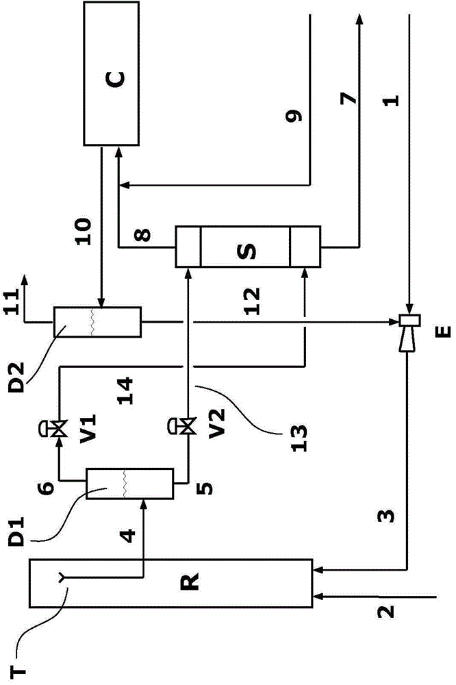
[0105] According to the present invention, the method for realizing urea synthesis is based on figure 1 program operation shown, which would contain CO 2 , NH 3 and an appropriate amount of O as a passivating agent 2 The gas stream of is fed to the bottom (base, base) of the stripping column (S), in addition to the inert products from the gas-liquid separation unit (D1) and traces of water. No further volumes of air or other passivating agents are separately fed to the bottom of the stripper or other parts of the plant. refer to figure 1 The scheme shown in and the nominal (nominal) production of urea of ​​1,000 kg / h. Impurities present at flow rates below 0.5 kg / h are ignored, such as, for example, hydrogen, helium, metal salts.

[0106] The following products are separately fed to the reactor (R):

[0107] - 730 kg / h of CO as a gas stream through line 2 at 120 °C and 16.3 MPa 2 and 8kg / h of air;

[0108] - 492 kg / h of CO via line 3 as a solution of ammonium carbamate...


PUM


Abstract

A process for the direct synthesis of urea from ammonia and carbon dioxide with increased corrosion resistance, comprising, in the high-pressure synthesis section, a reaction step in a vertical reactor (R) fed with at least one stream of fresh carbon dioxide containing a passivating agent and a decomposition-stripping step of the non-converted reagents, wherein the gas-liquid mixture collected at the head of the reactor is separated into a gaseous stream and a liquid stream fed to the tail and head of the stripper, respectively.

Description

technical field [0001] The present invention relates to an enhanced process for the synthesis of urea containing a passivation stream at the bottom of a stripper. Background technique [0002] In particular, many methods are known in the prior art for the production of urea. [0003] The synthesis of urea is achieved by reacting ammonia and carbon dioxide at high pressure and temperature, followed by separation of urea from the mixture containing unreacted products and recycling it to the reactor. [0004] Therefore, all industrial processes for the preparation of urea are based on a direct synthesis according to the following reaction: [0005] [0006] The synthesis proceeds in two distinct reaction steps: [0007] [0008] [0009] In the first step (1a), an exothermic equilibrium reaction with a high reaction rate takes place at room temperature, however, in step (1b), where high temperatures are necessary, high pressures are required to achieve a favorable eq...

Claims


Application Information

Patent Timeline
Patent Type & Authority Applications(China)
IPC IPC(8): C07C273/04
CPCC07C273/04B01D3/009Y02P20/141Y02P20/582
Inventor 利诺·卡莱西亚历山德罗·贾纳扎
Owner SAIPEM SPA
Why Eureka
Try Eureka