
Grating shear wave aberration detection interferometer and detection method thereof

A shear wave and interferometer technology, applied in the field of grating shear wave aberration detection interferometer, can solve the problems of increasing human error, eliminating system error, geometric optical path error and large detector tilt error

Active Publication Date: 2014-11-26
SHANGHAI INST OF OPTICS & FINE MECHANICS CHINESE ACAD OF SCI
View PDF7 Cites 13 Cited by
  • Summary
  • Abstract
  • Description
  • Claims
  • Application Information

AI Technical Summary

Problems solved by technology

Although the above method can improve the detection accuracy of wave aberration to a certain extent, it is necessary to use auxiliary means to eliminate the detector tilt error, or to perform theoretical calculations based on pre-measured corresponding data, and subtract the theoretical system from the experimental data. The system error has not been eliminated according to the actual experimental conditions, the residual geometric optical path error and the detector tilt error are relatively large, or multiple measurements are required, which increases human error, etc.

Method used


Image

  • Grating shear wave aberration detection interferometer and detection method thereof
  • Grating shear wave aberration detection interferometer and detection method thereof
  • Grating shear wave aberration detection interferometer and detection method thereof

Examples


Embodiment Construction

[0106] The present invention will be further described below with reference to the embodiments and the accompanying drawings, but the protection scope of the present invention should not be limited by the embodiments.

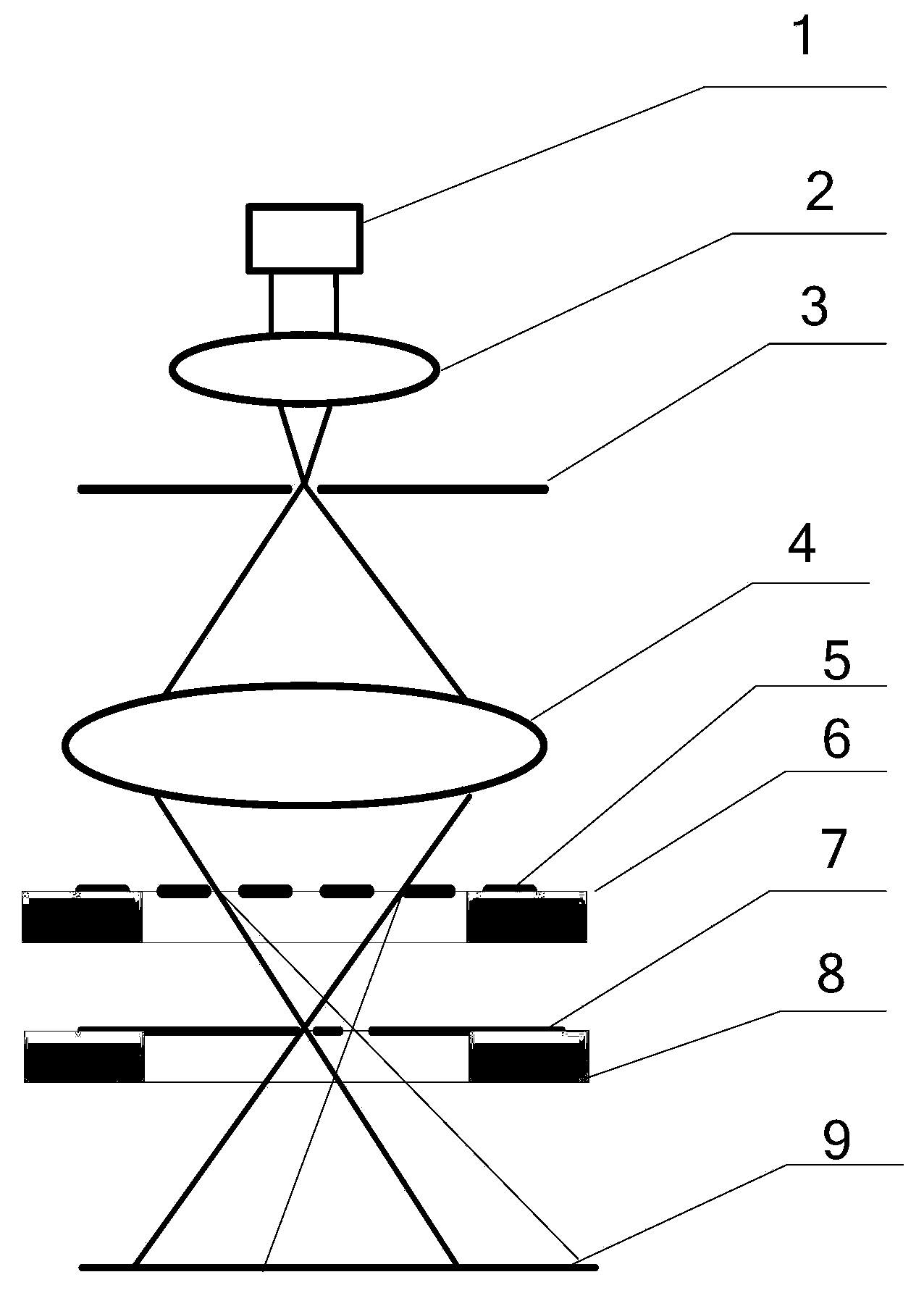
[0107] see first figure 1 , figure 1 It is the optical path diagram of the grating shear wave aberration detection interferometer of the present invention. It can be seen from the figure that the grating shear wave aberration detection interferometer of the present invention includes a light source 1. Along the light beam propagation direction of the light source 1, the focusing mirror 2 and the filter are in order. Hole 3, two-dimensional grating 5, grating displacement table 6, diaphragm plate 7, diaphragm alignment displacement table 8 and two-dimensional photoelectric sensor 9; the two-dimensional grating 5 is placed on the grating displacement table 6, and the The diaphragm plate 7 is placed on the diaphragm alignment displacement stage 8; the optical sys...


PUM


Abstract

The invention provides a grating shear wave aberration detection interferometer. The grating shear wave aberration detection interferometer comprises a light source, a focus lens, a filtering pinhole, a two-dimensional grating, a grating displacement platform, a diaphragm plate, a diaphragm alignment displacement platform and a two-dimensional photoelectric sensor. According to the grating shear wave aberration detection interferometer, the wave aberration of an optical system to be detected is detected; when the optical system to be detected is illuminated by the light source, the wavefront of the optical system to be detected generates an interference pattern through grating separation and shear, wavefront reconstruction is conducted on differential information generated by multiple diffraction levels in different directions through shear and interference, so that a system error correlative is obtained, and then the relevant parameters, namely, the distance between every two adjacent focusing points of different levels of diffraction light and the inclination angle of a detector, of main system error terms influencing the wave aberration detection precision of the grating shear interferometer are obtained; in this way, geometric path-length errors and detector inclination errors existing in wave aberration detection are eliminated, and the precision of wavefront reconstruction and the accuracy of wave aberration detection are improved. By the adoption of the grating shear wave aberration detection interferometer, wave aberration detection of the optical system to be detected is conducted, system errors existing during detection are eliminated, and the detection precision is improved.

Description

technical field [0001] The invention relates to a grating shearing interferometer, in particular to a grating shearing wave aberration detection interferometer and a detection method thereof. Background technique [0002] Grating shear interferometer is an important form of wavefront sensor, which has the advantages of simple structure, no need for a separate reference wavefront, easy to achieve common optical path interference, and anti-environmental interference. There are systematic errors in the grating shearing interferometer such as geometric optical path error, grating diffraction error, grating position offset and detector tilt, which affect the detection accuracy of wave aberration; especially for the application of wave aberration detection in high-precision optical systems, it will be The measuring optical system has a certain numerical aperture (NA), the collimation difficulty of the system and the systematic error increase with the numerical aperture, and the wa...

Claims


Application Information

Patent Timeline
Patent Type & Authority Applications(China)
IPC IPC(8): G01M11/02
Inventor 李杰唐锋王向朝戴凤钊吴飞斌李永
Owner SHANGHAI INST OF OPTICS & FINE MECHANICS CHINESE ACAD OF SCI
Learn More