Flat-plate-type transverse magnetic flux switching permanent magnet linear motor

A technology of permanent magnet linear motor and transverse flux, applied in the direction of electrical components, electromechanical devices, electric components, etc., can solve the problems of uneven change of permanent magnet reluctance, difficult design of small pole pitch motors, insufficient utilization of iron cores, etc. , achieve low short-circuit demagnetization risk, improve winding utilization, simple structure and production process

Inactive Publication Date: 2014-11-26
SOUTHEAST UNIV
View PDF13 Cites 7 Cited by
  • Summary
  • Abstract
  • Description
  • Claims
  • Application Information

AI Technical Summary

Problems solved by technology

[0005] Purpose of the invention: In order to overcome the insufficient utilization of the existing magnetic flux switching permanent magnet linear motor windings, permanent magnets, and iron cores, the uneven change of permanent magnet reluctance introduces thrust fluctuations, and the coupling between the pole pitch and the motor cogging size causes the motor with small pole pitch to be relatively heavy. It is difficult to design, and the lamination scheme is not ideal, or the reluctance jumps or cannot be laminated, resulting in large core loss; the invention provides a flat-plate transverse flux switching permanent magnet linear motor, which adopts the Properly matching the bent stator core can make the structure of the secondary stator core simple, the lamination and assembly of the primary armature are not complicated, and the side ends of the motor winding are small, the permanent magnet reluctance changes evenly, and the permanent magnet utilization rate is improved. , The decoupling of motor pole pitch and tooth slot size is convenient for motor design, and finally achieves the beneficial effects of better control performance of flux switching permanent magnet linear motor, improved material utilization rate, reduced loss, and simple processing

Method used


Image

  • Flat-plate-type transverse magnetic flux switching permanent magnet linear motor
  • Flat-plate-type transverse magnetic flux switching permanent magnet linear motor
  • Flat-plate-type transverse magnetic flux switching permanent magnet linear motor

Examples


Embodiment Construction

[0026] The present invention will be further described below in conjunction with the accompanying drawings.

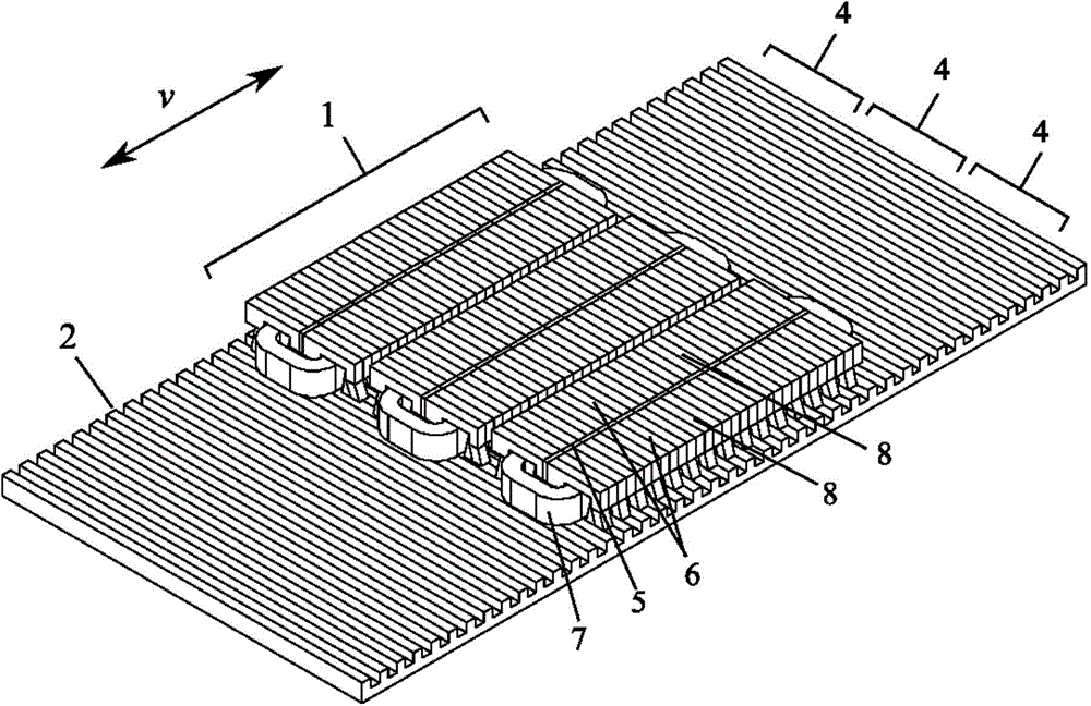
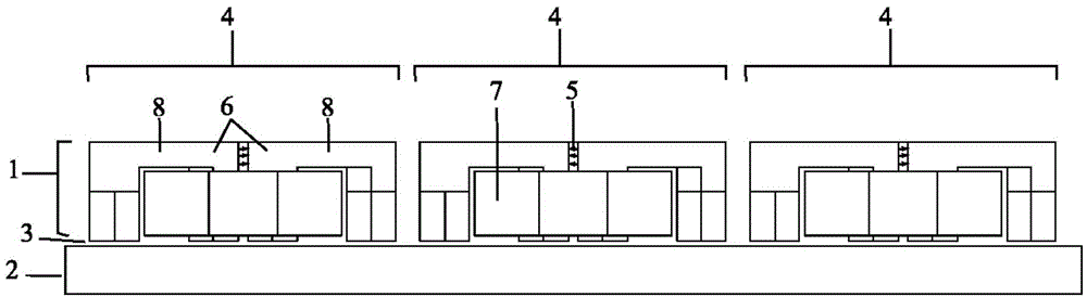
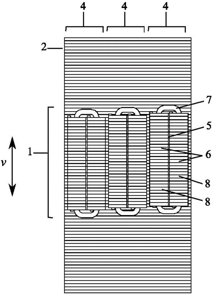
[0027] like figure 1 , figure 2 , image 3 , Figure 4 Shown is a flat-type transverse flux switching permanent magnet linear motor, including a flat-type motor primary 1 and a flat-type motor secondary 2, the motor primary 1 and the motor secondary 2 are installed opposite each other, and an air gap surface 3 is left in the middle. The primary 1 is installed with a permanent magnet 5 and a winding 7, and works on the principle of magnetic flux switching; the primary 1 of the motor includes more than one primary unit 4, and the phases of the multi-phase motor are electromagnetically decoupled; the primary unit 4 includes a primary unit core 6 , the primary unit core 6 is composed of two primary unit core blocks 8 perpendicular to the moving direction v, the primary unit core block 8 is formed by laminating primary electrical steel sheets 9 along the moving directio...


PUM


Abstract

The invention discloses a flat-plate-type transverse magnetic flux switching permanent magnet linear motor. The motor comprises a flat-plate-type motor primary and a flat-plate-type motor secondary, wherein the motor primary and the motor secondary are oppositely installed, an air gap face is arranged between the motor primary and the motor secondary, and permanent magnets and windings are installed on the motor primary and operate based on a magnetic flux switching principle. The motor is characterized in that the motor primary further comprises one or more primary units, each primary unit comprises a primary unit iron core, each primary unit iron core is composed of two primary unit iron core blocks perpendicular to the moving direction v, and the primary unit iron core blocks are formed by overlapping primary electrical steel sheets in the moving direction v; the motor secondary is formed by overlapping secondary electrical steel sheets in the moving direction v. The motor has the advantages that the structure and the production technology are simple, the primary and the secondary can be overlapped for reducing iron loss, the utilization rate of the permanent magnets and the windings is high, a permanent magnetic circuit is even in magnetic conductance and small in positioning force and eddy current, power thrust is only related to the length of the motor, and rapid designing in batches can be performed.

Description

technical field [0001] The invention relates to a flat-plate transverse magnetic flux switching permanent magnet linear motor, which belongs to a linear servo motor. Background technique [0002] There are a large number of linear motion modes in the industrial field, and many of these motion modes still use rotary motors as drives, and then convert them into linear motion with a large number of mechanical components such as crankshafts and reduction gears. These intermediate conversion components not only consume a lot of energy, increase the risk of system failure and maintenance costs, but also mostly make the working mode control single and difficult to change. Direct drive technology was created to solve such difficulties, and in order to simplify the conversion mechanism of the system, the linear drive needs to have better electrical and control performance than the rotary drive. Existing linear actuators are mainly divided into several types of motors according to th...

Claims


Application Information

Patent Timeline
Patent Type & Authority Applications(China)
IPC IPC(8): H02K41/03
Inventor 余海涛施振川沈蛟骁陈辉陈浩
Owner SOUTHEAST UNIV
Why Eureka
Try Eureka