
Formaldehyde gas sensor

A formaldehyde gas and sensor technology, applied in instruments, scientific instruments, measuring devices, etc., can solve the problems of high production cost, high sensor cost, and short service life, and achieve stable detection results, high detection sensitivity, and low production cost Effect

Inactive Publication Date: 2014-12-03
WUHAN UNIV OF TECH
View PDF7 Cites 17 Cited by
  • Summary
  • Abstract
  • Description
  • Claims
  • Application Information

AI Technical Summary

Problems solved by technology

Pure precious metals are used as working electrodes, which have high production costs, poor electrochemical performance, and poor detection sensitivity; concentrated sulfuric acid is highly corrosive, so electrode materials and electrolytic cells are easily corroded, and the service life is not long, resulting in unstable detection results
[0004] Invention patent CN101776640A discloses a formaldehyde gas sensor that can detect the concentration of formaldehyde on site, which includes a support shell, an air intake shell, a membrane-electrode complex and a porous gasket. The membrane-electrode complex is directly hot-pressed with a noble metal catalyst Coated on the surface of the electrolyte as the working electrode and the counter electrode, the disadvantages are: the amount of precious metal is too large, the cost of the sensor is high; the use of hot pressing process causes permanent damage to the solid polymer electrolyte, the chemical resistance of the electrolyte, mechanical properties, protons, etc. The conductivity is correspondingly deteriorated; the catalyst is directly used as an electrode, and it is impossible to obtain a significant current density due to mass transfer limitations during the sensor detection process, and the detection sensitivity is poor and low concentrations cannot be detected

Method used


Image

  • Formaldehyde gas sensor
  • Formaldehyde gas sensor
  • Formaldehyde gas sensor

Examples


Embodiment Construction

[0023] The present invention will be further described below in conjunction with the accompanying drawings and embodiments, but the content of the present invention is not limited to the following embodiments.

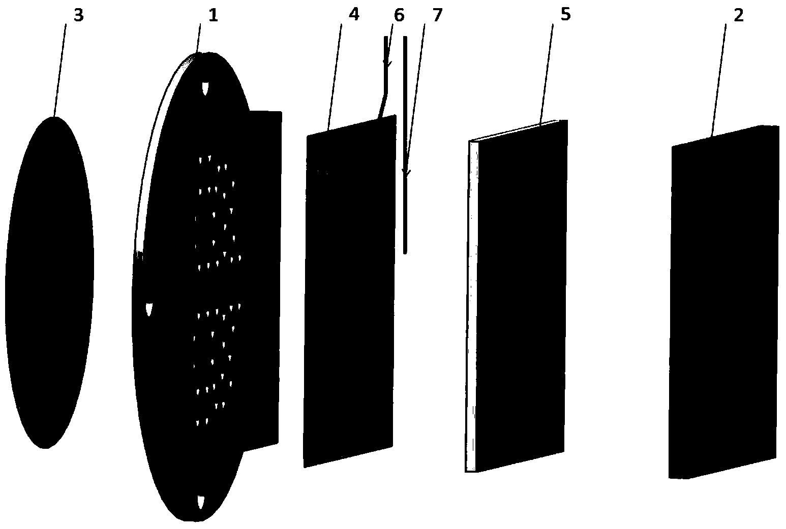
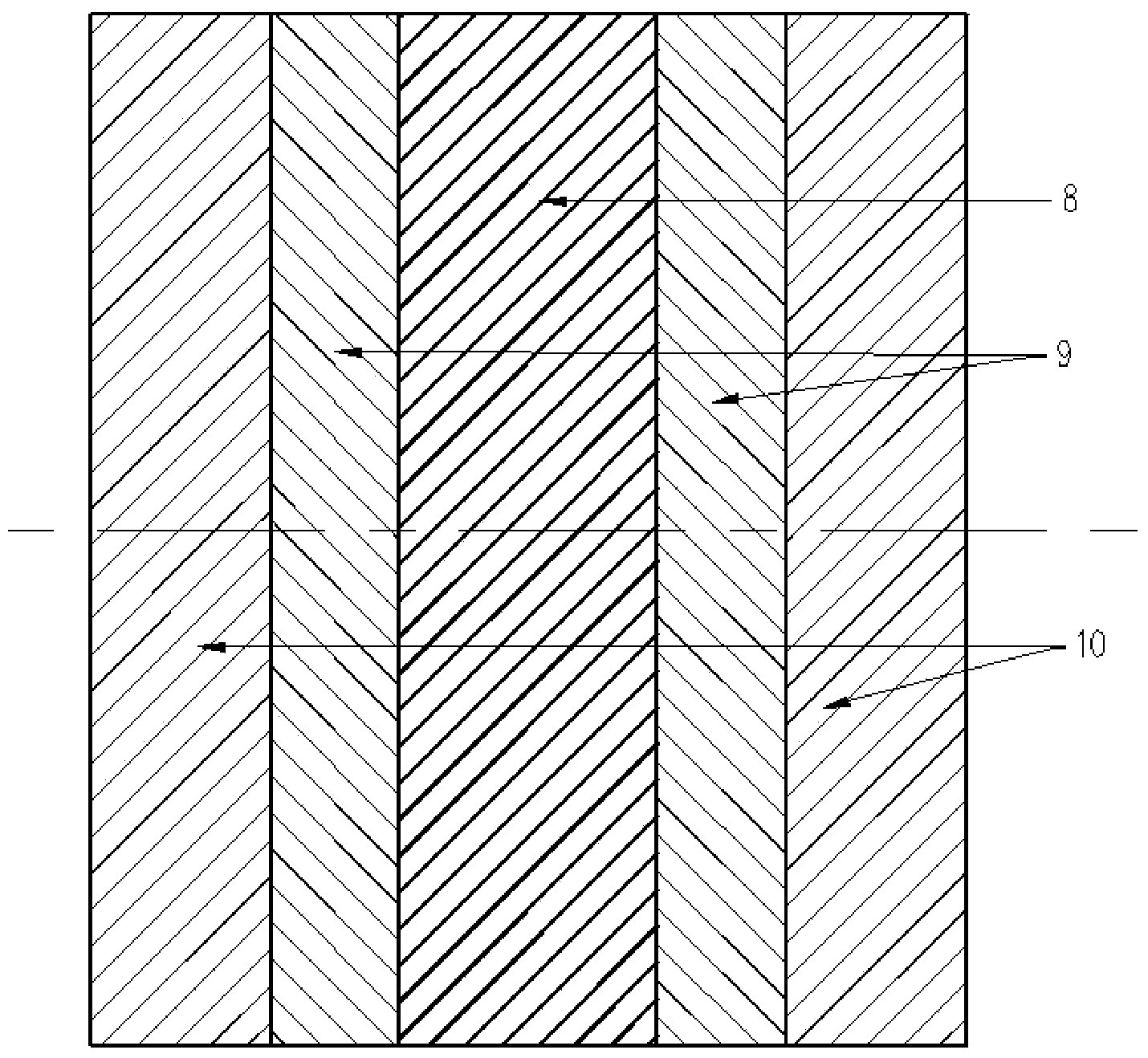
[0024] figure 1 It is the structural representation of formaldehyde gas sensor of the present invention, as figure 1 As shown, the formaldehyde gas sensor provided by the present invention includes: an air inlet filter membrane 3 , an air inlet casing 1 , an anode lead 6 , a membrane electrode assembly 4 , a cathode lead 7 , a cavity support 5 and a sealed casing 2 .

[0025] Among them, the air inlet shell 1 with the air inlet and the sealed shell 2 embedded in it form a hollow closed shell, and the hollow closed shell is from left to right, and the anode lead 6, the membrane electrode assembly 4, and the cathode lead 7 are respectively placed inside. The cavity support body 5 and the air inlet filter membrane 3 are attached outside the air inlet of the air inlet she...


PUM


Abstract

The invention provides a formaldehyde gas sensor. The formaldehyde gas sensor comprises a gas inlet housing, a seal housing, a gas inlet filter membrane, a membrane electrode module, a cavity support, an anode lead and a cathode lead, wherein the gas inlet housing is provided with a gas inlet; the gas inlet filter membrane is attached to the exterior of the gas inlet of the gas inlet housing; the seal housing is embedded in the gas inlet housing to form a hollow closed housing; the anode lead, the membrane electrode module, the cathode lead and the cavity support are orderly arranged in the closed housing from left to right; the membrane electrode module comprises a solid polymer electrolyte, and an anode and a cathode which are arranged on the two sides of the solid polymer electrolyte, respectively; the anode and the cathode both are gas diffusion electrodes, and each gas diffusion electrode comprises a two-layer structure with a gas diffusion layer and a catalytic layer. The formaldehyde gas sensor is capable of detecting tested gas at normal temperature, and is low in production cost, long in service life, high in detection sensitivity and stable in detection result.

Description

technical field [0001] The invention relates to a formaldehyde gas sensor. Background technique [0002] Indoor air pollutants mainly include formaldehyde (HCHO), benzene series and volatile organic compounds, etc. The first prerequisite for improving indoor air quality is the inspection of indoor air pollutants, and the realization of indoor air pollutants such as formaldehyde, benzene series, etc. Real-time and accurate on-site inspection and identification are two key technologies for controlling indoor air quality. Therefore, the development of sensors that can detect various harmful gases in real time has attracted the attention of various countries. Artificial boards such as density boards and particle boards, decoration materials such as adhesives and wallpapers, chemical fiber textiles, disinfectants and other daily necessities will emit formaldehyde, and incomplete combustion of fossil fuels such as liquefied petroleum gas will also release formaldehyde, so there i...

Claims


Application Information

Patent Timeline
Patent Type & Authority Applications(China)
IPC IPC(8): G01N27/407
Inventor 陈磊詹明梁聪
Owner WUHAN UNIV OF TECH
Learn More