
Flyback switching power supply

A switching power supply and flyback technology, which is applied in the direction of electrical components, adjusting electrical variables, instruments, etc., can solve the problem of large power consumption

Active Publication Date: 2014-12-03
SUZHOU INOVANCE TECH CO LTD
View PDF4 Cites 14 Cited by
  • Summary
  • Abstract
  • Description
  • Claims
  • Application Information

AI Technical Summary

Problems solved by technology

[0008] The technical problem to be solved by the present invention is to provide a solution for the problem of device damage caused by the inaccurate current limit point of the flyback switching power supply in continuous current mode when overload or short circuit and the problem of large power consumption when adding a power limiting resistor. A flyback switching power supply with a power-limiting unit, which enables the switch to improve the accuracy of the power-limiting point when the high-voltage input is overloaded or short-circuited, prevents the device from being damaged by over-current, and reduces the power consumption of the power-limiting unit

Method used


Image

  • Flyback switching power supply
  • Flyback switching power supply
  • Flyback switching power supply

Examples


Embodiment Construction

[0018] In order to make the object, technical solution and advantages of the present invention clearer, the present invention will be further described in detail below in conjunction with the accompanying drawings and embodiments. It should be understood that the specific embodiments described here are only used to explain the present invention, not to limit the present invention.

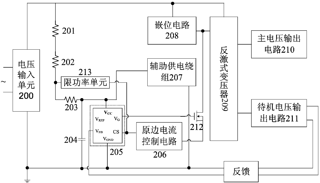
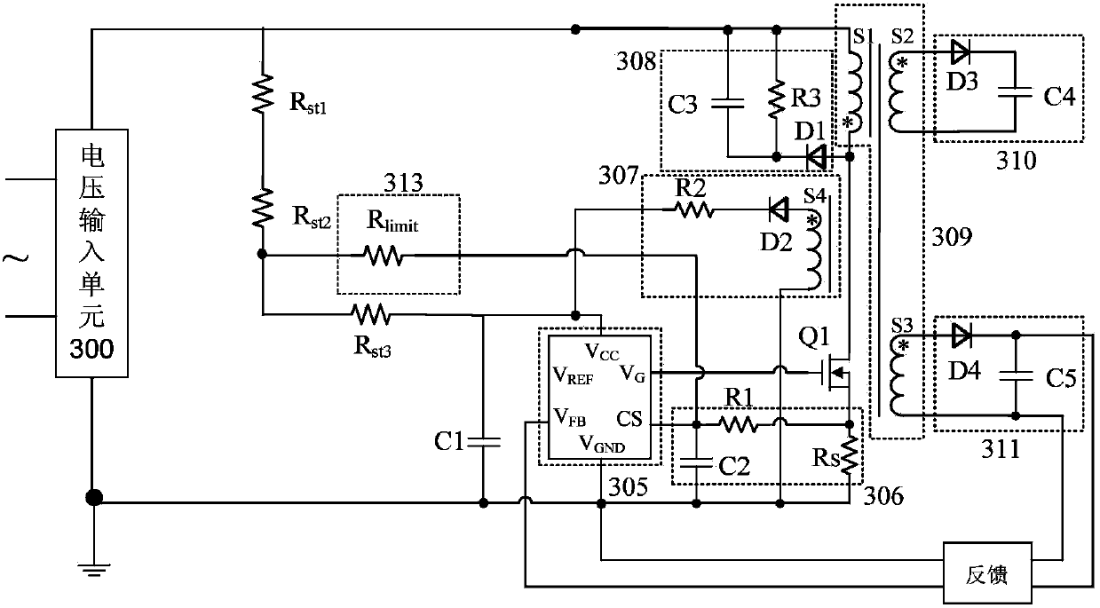
[0019] refer to figure 2 , figure 2 It is a circuit structure diagram of a flyback switching power supply of the present invention, the flyback switching power supply includes a voltage input unit 200, a first starting resistor 201, a second starting resistor 202, a third starting resistor 203, and a first capacitor 204 , peak current control chip 205, primary current detection circuit 206, auxiliary power supply winding 207, clamping circuit 208, flyback transformer 209, main voltage output circuit 210, standby voltage output circuit 211, first power switch tube 212 and limiter Power unit 213;...


PUM


Abstract

The invention provides a flyback switching power supply, which comprises a voltage input unit, a first starting resistor, a second starting resistor, a third starting resistor, a first capacitor, a peak current control chip, a primary side current detection circuit, an auxiliary power supply winding, a clamping circuit, a flyback transformer, a main voltage output circuit, a standby voltage output circuit, a first power switching tube and a power limiting unit, wherein one end of the power limiting unit is connected to the voltage input unit through the first starting resistor and the second starting resistor which are connected in series, and the other end of the power limiting unit is connected to a CS pin of the peak current control chip. The flyback switching power supply improves an overload or short-circuit protection ability when high voltage is inputted, devices are prevented from being damaged by overcurrent, and the power consumption of the power limiting unit is reduced.

Description

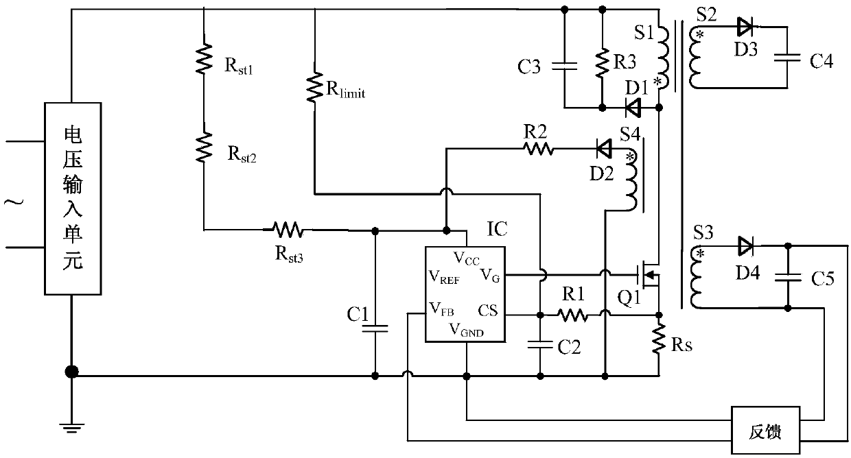
technical field [0001] The invention relates to the field of circuits, in particular to a flyback switching power supply with improved overload protection capability. Background technique [0002] The flyback switching power supply is widely used in the power supply of electronic products due to its advantages of low cost and small size. In a larger power flyback switching power supply system, a single-tube flyback switching power supply is usually selected and designed to work in a continuous conduction mode. [0003] figure 1 It is a circuit diagram of a flyback switching power supply in continuous current mode in the prior art. The principle of overload or short circuit protection of this circuit is: when overload or short circuit occurs, the current detection pin of the peak current control chip (such as UC2844) detects the primary side When the current reaches the upper limit of 1V, the drive signal of the switch tube is turned off, the rise of the primary current is ...

Claims


Application Information

Patent Timeline
Patent Type & Authority Applications(China)
IPC IPC(8): H02M7/217H02M3/335
Inventor 刘志军
Owner SUZHOU INOVANCE TECH CO LTD
Learn More