Waste gas purifying device applicable to incinerator

An exhaust gas purification device and exhaust gas purification technology are applied in the direction of chemical instruments and methods, dispersed particle separation, separation methods, etc., which can solve the problems of easy explosion and other problems, and achieve the effect of increasing path and time, good filtering effect, and increasing contact area

Active Publication Date: 2014-12-10
广州拉斯卡工程技术有限公司
View PDF9 Cites 21 Cited by
  • Summary
  • Abstract
  • Description
  • Claims
  • Application Information

AI Technical Summary

Problems solved by technology

[0004] In order to solve the above-mentioned deficiencies in the prior art, the present invention proposes a waste gas purification device suitable for incinerators, which includes an incinerator body and a waste gas inlet pipe connected to the exhaust port of the incinerator body. The end is connected with the dust collector. There are upper dust removal baffles and lower dust removal baffles in the dust collector. The upper dust removal baffles and the lower dust removal baffles are arranged alternately. The end of the exhaust chimney is connected to the exhaust chimney. On the inner wall of the exhaust chimney, there are left and right support plates that are staggered up and down. The gas spray desulfurization device, the exhaust gas purification pool is formed at the bottom of the exhaust chimney. The invention is simple to manufacture and install, and occupies a small area. Exhaust gas pollution problems, and avoid the risk of explosion caused by excessive air pressure inside the device

Method used


Image

  • Waste gas purifying device applicable to incinerator
  • Waste gas purifying device applicable to incinerator
  • Waste gas purifying device applicable to incinerator

Examples


Embodiment Construction

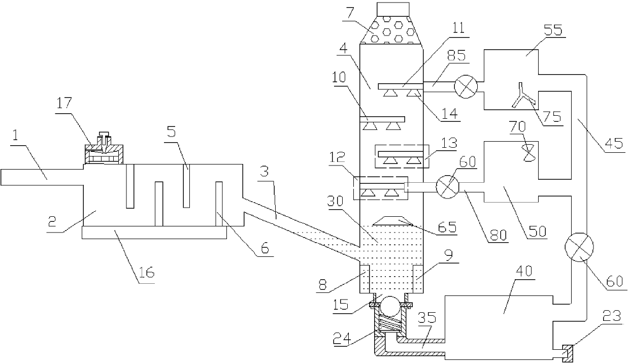
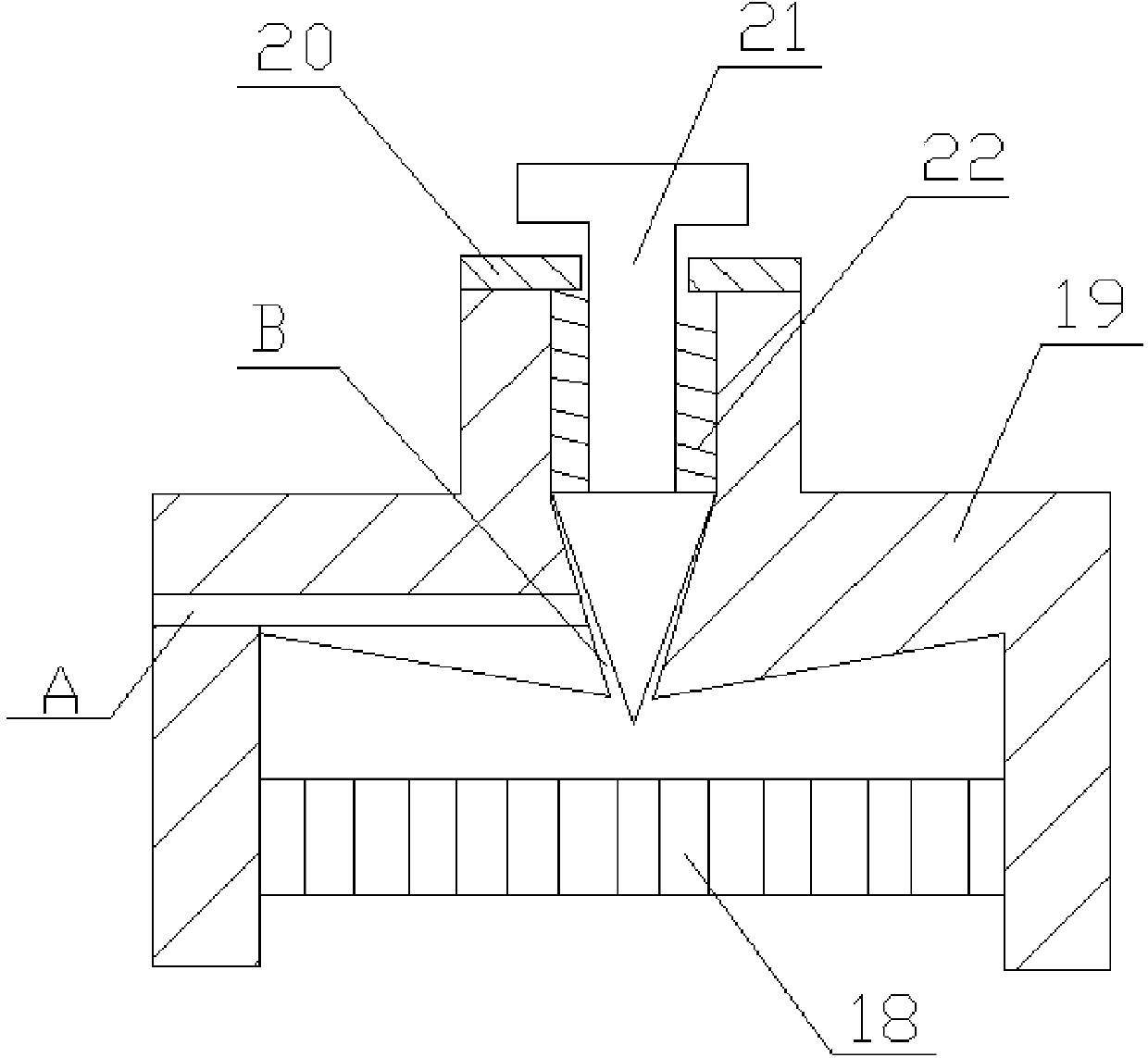
[0035] Such as Figure 1 to Figure 3 As shown, the first specific embodiment of the present invention is: an exhaust gas purification device suitable for an incinerator, including an incinerator body (not shown in the figure), and an exhaust gas inlet pipe communicated with the exhaust port of the incinerator body 1. The end of the exhaust gas inlet pipe 1 is connected to the dust collector 2, and the interior of the dust collector 2 is respectively provided with a plurality of upper dust removal baffles 5 and a plurality of lower dust removal baffles 6, and the upper dust removal baffles 5 and the lower dust removal baffles Plates 6 are arranged alternately at intervals, the upper dust removal baffle 5 is suspended on the inner wall of the upper end of the dust collector 2, the lower dust removal baffle 6 is fixed on the inner wall of the lower end of the dust collector 2, and the surfaces of the upper dust removal baffle 5 and the lower dust removal baffle 6 are provided with...


PUM


Abstract

The invention discloses a waste gas purifying device applicable to an incinerator. The waste gas purifying device comprises an incinerator waste gas purifying device body, and a waste gas inlet pipe communicated with the exhaust port of an incinerator body, wherein the tail end of the waste gas inlet pipe is communicated with a dust catcher; an upper dust removal baffle and a lower dust removal baffle are arranged in the dust catcher; the upper dust removal baffle and the lower dust removal baffle are arranged at intervals; the tail end of the dust catcher is communicated with a waste gas exhaust pipe; the tail end of the waste gas exhaust pipe is communicated with an exhaust chimney; a left supporting plate and a right supporting plate which are longitudinally staggered are arranged on the inner side wall of the exhaust chimney; a flue gas pre-spray heat sink is arranged on the left supporting plate; a flue gas pre-spray desulfurizer is arranged on the right supporting plate; a waste gas purifying tank is formed at the bottom of the exhaust chimney; a deslagging door is arranged at the bottom of the dust catcher; a pressure release valve is arranged at the top of the dust catcher. The waste gas purifying device can filter poisonous gas, heavy metal and dust produced during the combustion of fire coal, effectively solves the problem of waste gas pollution, and avoids the risk of explosion caused by overlarge air pressure inside the device.

Description

technical field [0001] The invention relates to a waste gas purification device, in particular to a waste gas purification device suitable for an incinerator, and belongs to the technical field of environmental protection devices. Background technique [0002] With the rapid development of science and technology, people pay more and more attention to environmental protection, and the requirements for air quality are also getting higher and higher. As a device for incinerating coal or waste in exchange for heat or waste treatment, its combustion The flue gas discharged through the incinerator after burning coal or waste contains a large amount of acid gas (such as sulfur-containing gas), dust, dioxins, heavy metals and other pollutants. If not properly treated, it will cause serious damage to the atmospheric environment. Serious pollution; in order to purify and treat the waste gas discharged from the incinerator, various schemes have been proposed in the prior art, such as t...

Claims


Application Information

Patent Timeline
Patent Type & Authority Applications(China)
IPC IPC(8): B01D45/08B01D53/78B01D53/48
Inventor 田钰徐鸿
Owner 广州拉斯卡工程技术有限公司
Why Eureka
Try Eureka