System for nanofluid minimal quantity lubrication electrostatic atomization controllable jet flow inner cooling technology

A micro-lubrication and electrostatic atomization technology, which is used in manufacturing tools, metal processing equipment, grinding/polishing safety devices, etc., and can solve problems such as the inability to generally adapt to mechanical processing, the large size of electrostatic atomization nozzles, and the inability to use machine tools. , to achieve the effect of improving lubrication and cooling effect, reducing particle spreading pollution and improving utilization rate

Active Publication Date: 2014-12-10
QINGDAO TECHNOLOGICAL UNIVERSITY
View PDF6 Cites 15 Cited by
  • Summary
  • Abstract
  • Description
  • Claims
  • Application Information

AI Technical Summary

Problems solved by technology

[0006] However, this system is only used in grinding processing conditions. The supply method of the minimum amount of lubrication cutting fluid is external injection, and the size of the electrostatic atomization nozzle is large and the precision is low. It cannot be used for internal cooling drilling, milling, boring machines, reamers, etc. Machine Tool
Therefore, the system cannot be generally adapted to machining, especially machining with internal cooling tools.

Method used


Image

  • System for nanofluid minimal quantity lubrication electrostatic atomization controllable jet flow inner cooling technology
  • System for nanofluid minimal quantity lubrication electrostatic atomization controllable jet flow inner cooling technology
  • System for nanofluid minimal quantity lubrication electrostatic atomization controllable jet flow inner cooling technology

Examples


Embodiment Construction

[0064] The present invention is described below in conjunction with accompanying drawing.

[0065] The first embodiment of the present invention is Figures 1 to 12 As shown, it is about the technological method and equipment of nanofluid micro-lubrication electrostatic atomization controllable jet internal cooling.

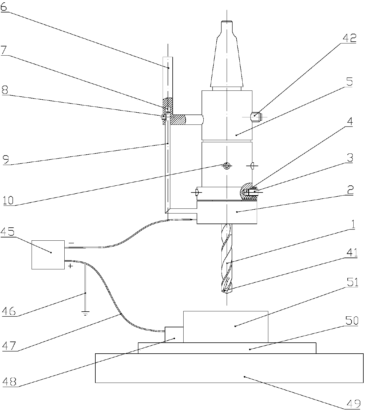
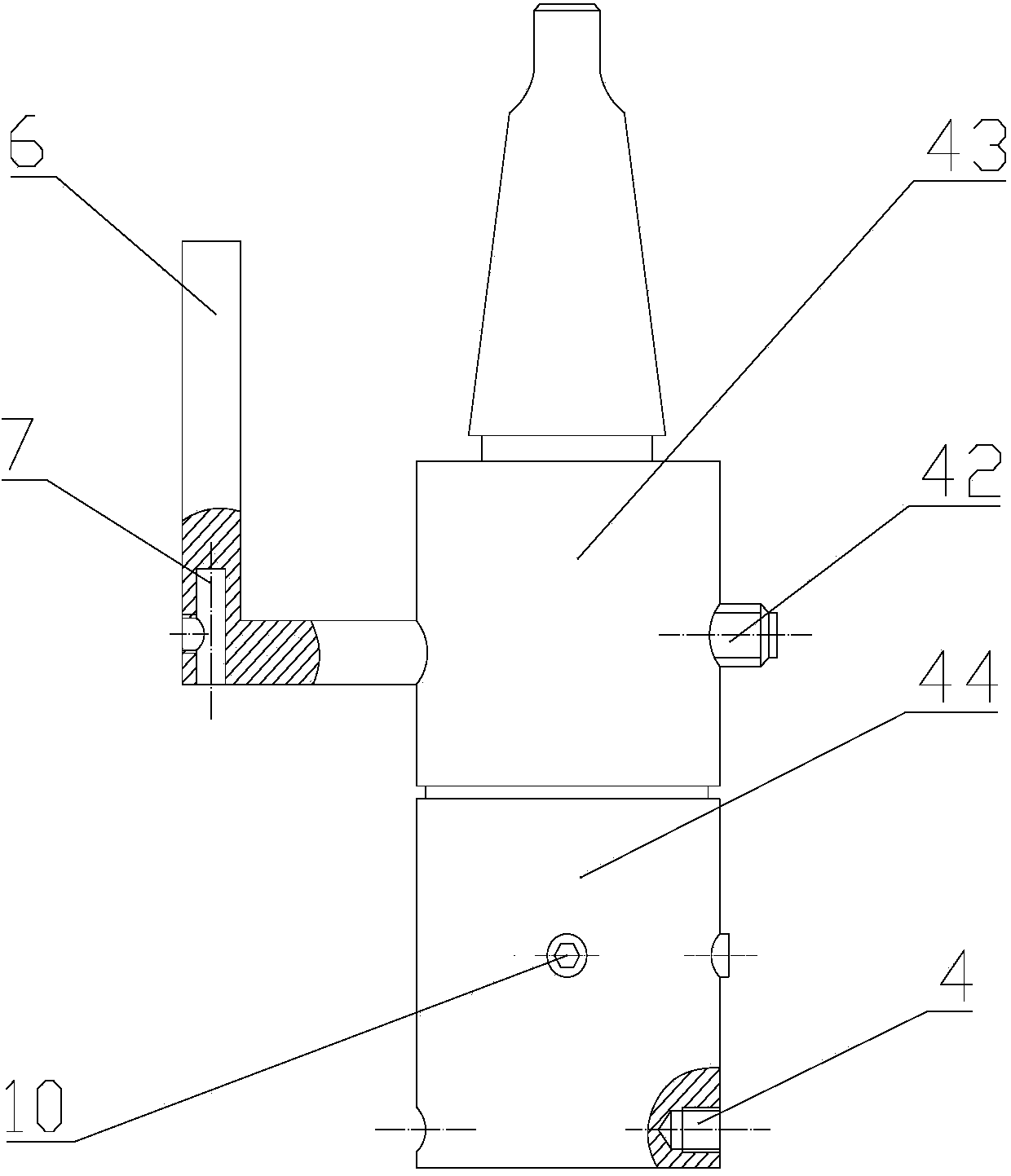
[0066] Such as figure 1 As shown, the internal cooling drill bit 1 is clamped by the internal cooling tool converter 5, and the internal cooling drill bit 1 is positioned and clamped by two hexagon socket head screws III 10 to the rotating part of the internal cooling tool converter 5; the internal cooling tool converter 5 The fixed part of the internal cooling tool converter is connected to the positioning hole of the machine tool by the positioning shaft 6 of the internal cooling tool converter to realize the positioning of the fixed part of the internal cooling tool converter 5; the minimum quantity lubrication system is connected to the fixed part of the int...


PUM


Abstract

The invention relates to a system for the nanofluid minimal quantity lubrication electrostatic atomization controllable jet flow inner cooling technology. According to the system for the nanofluid minimal quantity lubrication electrostatic atomization controllable jet flow inner cooling technology, based on the electrostatic atomization principle, minimal quantity lubrication cutting fluid fog droplets can be controllably distributed during jetting, the evenness of a fog droplet spectrum can be improved, the deposition efficiency can be improved, the fluid effective utilization rate can be increased, the motion law of the fog droplets can be effectively controlled, in this way, pollution to the environment is reduced, and better health security is provided for workers. The system comprises an adjustable high-voltage direct-current power supply, an inner-cooled cutter converter, a high-voltage electricity converting device and an integrated spray nozzle. A minimal quantity lubrication system supplies minimal quantity lubrication cutting liquid to an inner-cooled drill bit through the inner-cooled cutter converter. The adjustable high-voltage direct-current power supply conducts positive electricity to a needle electrode of the integrated nozzle through the high-voltage electricity converting device, the adjustable high-voltage direct-current power supply makes negative electricity be grounded and transmits the negative electricity to a workpiece through an electromagnetic connector, and then a corona charging field is formed in the needle electrode-workpiece area; in this way, corona charging is conducted on the minimal quantity lubrication cutting fluid, and then electrostatic atomization function is achieved.

Description

technical field [0001] The invention relates to an electrostatic atomization device for nano-particle micro-lubrication cutting fluid in mechanical processing, in particular to a system for nano-fluid micro-lubrication electrostatic atomization controllable jet internal cooling process. Background technique [0002] Minimal Quantity Lubrication technology, also known as MQL (Minimal Quantity Lubrication) technology, is to mix a very small amount of lubricating fluid with compressed air with a certain pressure and atomize it, spray it into the grinding area, and control the contact between the grinding wheel and the grinding debris, and the grinding wheel and the workpiece. effectively lubricate the surface. Under the premise of ensuring effective lubrication and cooling effect, this technology uses the minimum amount of grinding fluid (about a few thousandths of the amount used in traditional pouring lubrication methods) to reduce costs, environmental pollution and human dam...

Claims


Application Information

Patent Timeline
Patent Type & Authority Applications(China)
IPC IPC(8): B24B55/02B24B57/02
CPCB24B55/02B24B57/02
Inventor 张彦彬李长河贾东洲张东坤
Owner QINGDAO TECHNOLOGICAL UNIVERSITY
Why Eureka
Try Eureka