Automatic centering and clamping device based on transmission of worm and worm gears and crank connecting rods

A crank connecting rod and automatic centering technology, applied in the mechanical field, can solve the problems of many intermediate links in energy transmission and conversion, affecting the stability and accuracy of motion, hydraulic transmission can not guarantee the transmission ratio, etc., to shorten the time to adjust the fixture , Realize multi-directional clamping and clamping direction conversion, and expand the effect of clamping range

Inactive Publication Date: 2014-12-17
SUZHOU POLYTECHNIC INST OF AGRI
View PDF4 Cites 5 Cited by
  • Summary
  • Abstract
  • Description
  • Claims
  • Application Information

AI Technical Summary

Problems solved by technology

The advantage of the manual clamp is that it is environmentally friendly, but it has a fatal disadvantage, that is, due to the limited force of the human hand, the clamping force cannot be very large
Pneumatic and hydraulic fixtures use hydraulic oil or compressed air as the working medium for energy transmission and control. There are many intermediate links in energy transmission and conversion, long routes, and large energy losses.
In addition, pneumatic and hydraulic transmission will also cause environmental pollution due to the leakage and volatilization of hydraulic oil or compressed gas as the transmission medium. The leakage of hydraulic oil will also affect the stability and correctness of movement, so that hydraulic transmission cannot guarantee a strict transmission ratio.
The pure inching fixture in the electric fixture has the disadvantages of small force magnification of the intermediate mechanism, large volume, difficult change of spatial position, and large motor power.

Method used


Image

  • Automatic centering and clamping device based on transmission of worm and worm gears and crank connecting rods

Examples


Embodiment 1

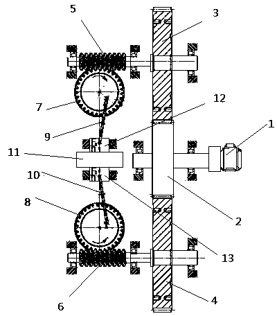
[0021] Such as figure 1 As shown, an automatic centering clamping device based on worm gear and crank connecting rod transmission includes an upper worm gear 7 and a lower worm gear 8 symmetrically arranged above and below the workpiece 11, each of which is hinged with a crank connecting rod, The end of the upper crank connecting rod 9 is connected with an upper pressure head 12, and the end of the lower crank connecting rod 10 is connected with a lower pressure head 13. The upper and lower pressure heads respectively drive the crank connecting rod through the rotation of the upper and lower worm wheels to clamp the pressure head. Workpiece 11. Wherein, the upper worm wheel 7 is driven by an upper worm 5 meshed with it, the lower worm wheel 8 is driven by a lower worm 6 meshed with it, and the upper and lower worms are respectively provided with an upper driven gear 3 and a lower driven gear 4, said Both driven gears are meshed on a driving gear 2, which is driven by a reduct...

Embodiment 2

[0026] The invention also discloses an automatic centering clamping device based on the transmission of worm gears and crank connecting rods, which includes three worm gears, the angles between the three worm gears are 120°, and the shaft center of each worm gear reaches the workpiece Each of the worm wheels is hinged with a crank connecting rod, and the end of the crank connecting rod is fixedly connected with a pressure head, and the pressure head drives the crank connecting rod through the rotation of the worm wheel to make the pressure head clamp the workpiece. Each worm gear is driven by a worm meshed with it, and each worm is provided with a driven gear, and each driven gear is meshed with a driving gear, and the driving gear is driven by a reduction motor, wherein the worm is a single Head worm, and the lead angle is less than 3.5°

[0027] The only difference between this embodiment 2 (not shown) and embodiment 1 is that there are three worm wheels with an angle of 120...

Embodiment 3

[0029] The invention also discloses an automatic centering clamping device based on the transmission of worm gears and crank connecting rods, which includes four worm gears, the angles between the four worm gears are 90°, and the axis center of each worm gear reaches the workpiece Each of the worm wheels is hinged with a crank connecting rod, and the end of the crank connecting rod is fixedly connected with a pressure head, and the pressure head drives the crank connecting rod through the rotation of the worm wheel to make the pressure head clamp the workpiece. Each worm gear is driven by a worm meshed with it, and each worm is provided with a driven gear, and each driven gear is meshed with a driving gear, and the driving gear is driven by a reduction motor, wherein the worm is a single Head worm, and the lead angle is less than 3.5°

[0030] The only difference between Embodiment 3 (not shown) and Embodiment 1 and Embodiment 2 is that it has four worm wheels at an angle of 9...


PUM


Abstract

The invention discloses an automatic centering and clamping device based on transmission of worm-worm gears and crank connecting rods. The automatic centering and clamping device comprises at least two worm gears, wherein each worm gear is hinged to a crank connecting rod; the tail ends of the crank connecting rods are fixedly connected with pressure heads; the pressure heads are used for driving the crank connecting rods through rotation of the worm gears to drive the pressure heads to clamp a workpiece; each worm gear is driven by a worm which is meshed with the worm gear respectively; each worm is provided with a driven gear; each driven gear is meshed on the same driving gear. According to the automatic centering and clamping device, the worm-worm gears and the crank connecting rod mechanisms are arranged symmetrically, and the output force generated by the pressure heads is equal in magnitude and reverse in directions, so that automatic centering and alignment are realized, the fixture adjusting time can be shortened, the workpiece machining efficiency is increased, and the effects of saving labor force, saving time and increasing efficiency are achieved.

Description

technical field [0001] The invention relates to an automatic centering clamping device based on the transmission of a worm gear and a crank connecting rod, which belongs to the technical field of machinery. Background technique [0002] With the advancement of science and technology, fixtures have developed from an auxiliary tool to a complete range of process equipment, which is an indispensable part of machining. Driven by the development of machine tool technology in the direction of high speed, high efficiency, precision, compound, intelligence and environmental protection, fixture technology is developing in the direction of high precision, high efficiency, module, combination, general purpose and economy. The power source of the fixture includes manual clamping, pneumatic clamping, hydraulic clamping and electric clamping. The advantage of the manual clamp is that it is environmentally friendly, but it has a fatal disadvantage, that is, due to the limited force of the...

Claims


Application Information

Patent Timeline
Patent Type & Authority Applications(China)
IPC IPC(8): B23Q3/00
CPCB23Q3/00
Inventor 夏春风过琦芳
Owner SUZHOU POLYTECHNIC INST OF AGRI
Why Eureka
Try Eureka