High voltage gain bidirectional DC-DC (direct current-direct current) converter based on switching capacitors and coupling inductors

A technology of DC-DC and switched capacitors, which is applied in the direction of adjusting electric variables, converting devices of output power, converting DC power input into DC power output, etc. Problems such as poor dynamic characteristics of automatic current sharing, to achieve the effect of reducing the capacity of the switch capacitor, simplifying the control sequence, and avoiding the problem of current sharing

Inactive Publication Date: 2014-12-17
TIANJIN UNIV
View PDF6 Cites 47 Cited by
  • Summary
  • Abstract
  • Description
  • Claims
  • Application Information

AI Technical Summary

Problems solved by technology

[0008] ③In some occasions where the input-output voltage conversion ratio is large, the switching device needs to work in an extreme duty cycle state, which is not conducive to the improvement of the efficiency of the converter, and limits the improvement of the operating frequency of the switching device
However, the large inductance and input and output filter capacitors lead to poor dynamic characteristics of automatic current sharing, and the converter is prone to current spikes or even instability. In addition, its highest efficiency in boost / buck mode is only 91% and 90%. %

Method used


Image

  • High voltage gain bidirectional DC-DC (direct current-direct current) converter based on switching capacitors and coupling inductors
  • High voltage gain bidirectional DC-DC (direct current-direct current) converter based on switching capacitors and coupling inductors
  • High voltage gain bidirectional DC-DC (direct current-direct current) converter based on switching capacitors and coupling inductors

Examples


Embodiment Construction

[0045] The technical solutions of the present invention will be further described in detail below in conjunction with the accompanying drawings and specific embodiments.

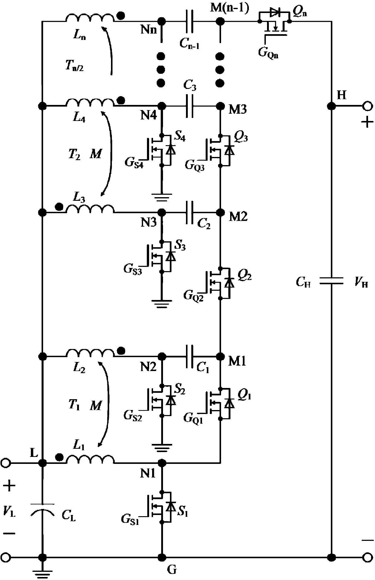
[0046] like figure 1 Shown, the present invention is based on the high voltage gain bidirectional DC-DC converter of switched capacitor and coupled inductor, and the structure of its circuit is: comprise N / 2 coupled inductors

[0047] T 1 [L 1 , L 2 ],T 2 [L 3 , L 4 ]...T (n / 2) [L (n-1) , L n ]; 2N high-frequency power switches S 1 , S 2 ... S n and Q 1 , Q 2 ... Q n ; N-1 high-frequency switched capacitors C 1 , C 2 ...C (n-1) ; and two input and output filter capacitors C L and C H ;

[0048] Coupled inductance T 1 ,T 2 ...T (N / 2) One end of the low-voltage side filter capacitor C L Connected, the connection node is recorded as the low-voltage side input / output node L, and the voltage of the low-voltage side input / output node is V L , filter capacitor C L The other end of is conne...


PUM


Abstract

The invention discloses a high voltage gain bidirectional DC-DC (direct current-direct current) converter based on switching capacitors and coupling inductors. The high voltage gain bidirectional DC-DC converter based on the switching capacitors and the coupling inductors is formed by combining Boost convertors, the coupling inductors and the switching capacitors in interleaved mode. An electric circuit of the high voltage gain bidirectional DC-DC converter based on the switching capacitors and the coupling inductors comprises n / 2 coupling inductors T1[L1, L2], T2[L3, L4]... T(n / 2)[L(n-1), Ln], 2n high frequency power switches S1, S2... Sn and Q1, Q2... Qn, N-1 high frequency switching capacitors C1, C2... C(n-1) and two input and output filter capacitors CL and CH. The high voltage gain bidirectional DC-DC converter based on the switching capacitors and the coupling inductors can effectively reduce current stress of a low voltage side power device and voltage stress of a high voltage side power device, further reduces the ripple of an input current and decrease the inductor size by using the coupling inductors, improves efficiency of an exchanger, and achieves bidirectional DC-DC conversion high in efficiency and high in voltage gain. According to high voltage gain bidirectional DC-DC converter based on the switching capacitors and the coupling inductors, an interleaved technology, a magnetic integration technology and a switching capacitor technology are combined, and therefore novel topology of the high voltage gain bidirectional DC-DC converter based on the switching capacitors and the coupling inductors not only has characteristics of being low in ripple of the input current and easy to design in EMT mode of an interleaved converter, but also achieves the purposes that a transformation ratio of input voltage and output voltage is large and switch voltage stress is low.

Description

technical field [0001] The invention relates to the technical field of high voltage gain and bidirectional DC-DC converters, and is a novel circuit with simple circuit structure, low voltage / current stress of switching devices, high efficiency and flexible expansion of boost ratio. Background technique [0002] With the rapid consumption of traditional fossil energy (such as oil, coal, natural gas, etc.), and the increasing problems of the world's energy crisis and environmental pollution, the rational development and utilization of green renewable energy has become an urgent need for human beings. . With the rapid consumption of traditional fossil energy (such as oil, coal, natural gas, etc.), and the increasing problems of the world's energy crisis and environmental pollution, the rational development and utilization of green renewable energy has become an urgent need for human beings. . For renewable energy, solar photovoltaic power generation, wind power generation and...

Claims


Application Information

Patent Timeline
Patent Type & Authority Applications(China)
IPC IPC(8): H02M3/155
Inventor 王议锋薛利坤王成山王萍
Owner TIANJIN UNIV
Why Eureka
Try Eureka