Tank bottom sludge discharging device for oilfield sedimentation tank

A technology of sludge discharge device and settling tank, which is applied to the feeding/discharging device of settling tank, etc., can solve the problems of shortening the service period of filter material, affecting the sewage treatment system, filter material pollution, etc., and achieves quick and convenient sludge cleaning. , the effect of saving water resources and running stably

Active Publication Date: 2014-12-24
大庆市考维尔自动化设备制造有限公司
View PDF6 Cites 10 Cited by
  • Summary
  • Abstract
  • Description
  • Claims
  • Application Information

AI Technical Summary

Problems solved by technology

[0002] At present, the water content of oilfield output liquid is relatively high. These sewage containing sewage oil, suspended solids, salts, heavy metals and other harmful substances will inevitably produce a large amount of sewage sludge during the treatment process of the settling tank. Due to the sludge It cannot be effectively discharged from the sludge discharge pipe, the effective volume of the tank is reduced, and the residence time of oily sewage in the settlement area is shortened, which affects the separation effect of oily sewage. If there is mud at the mouth of the water pipe, when the sludge at the bottom reaches a certain height, the oily sludge will enter the filter system together with the settled water, which will increase the processing load of the filter tank accordingly, causing serious pollution of the filter material and shortening the filtration time. The use cycle of raw materials affects the normal operation of the sewage treatment system, deteriorates the quality of sewage treatment, and increases the cycle of manual cleaning. In this way, it not only affects normal production, but also wastes a lot of manpower and financial resources.

Method used


Image

  • Tank bottom sludge discharging device for oilfield sedimentation tank
  • Tank bottom sludge discharging device for oilfield sedimentation tank

Examples


Embodiment Construction

[0014] The present invention will be further described below in conjunction with accompanying drawing:

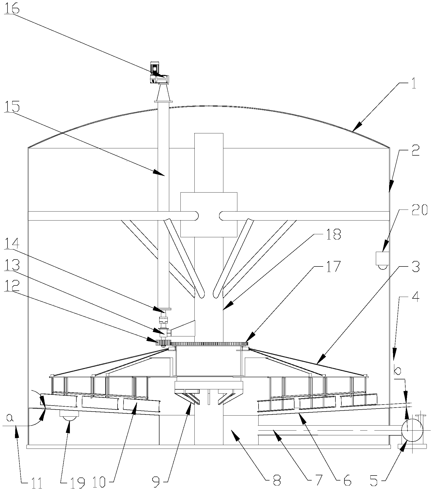
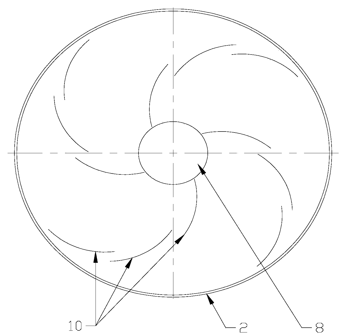
[0015] Depend on figure 1 combine figure 2 As shown, the mud discharge device at the bottom of the oilfield settling tank includes the tank roof 1 and the tank body 2 of the settling tank. The bottom of the tank body 2 is sealed and connected to a mud bearing bottom plate 6 along the inner wall of the tank body 2. The mud bearing bottom plate 6 is in a centripetal direction It is a circular steel plate in the shape of a downhill. There is a round hole in the center of the mud bearing bottom plate 6. The round hole elevation and the bottom plate of the settling tank are welded into a cylindrical mud collection chamber 8 with steel plates. The barrel wall of the mud collection chamber 8 is opened. There are through holes, which are airtightly welded with the mud discharge pipe 7. The mud discharge pipe 7 extends out of the tank body 2 and is connected to the inlet of the mu...


PUM

PropertyMeasurementUnit
velocityaaaaaaaaaa

Abstract

The invention provides a tank bottom sludge discharging device for an oilfield sedimentation tank. A tank body is provided with a sludge bearing bottom plate and a sludge collection chamber, the sludge collection chamber is connected with a sludge discharging pump, a sedimentation tank center pipe is connected with a center support connected with a driven gear, the driven gear is in meshed connection with a driving gear, a shaft of the driving gear is connected with a gear motor through a coupling, the gear motor is fixedly connected with a sleeving pipe outside the tank top, four groups of frameworks are fixedly and radially connected around a shaft of the driven gear, bottoms of the frameworks are connected with sludge scraping plates. Sludge is discharged through a tank bottom sludge removal system, the problem of sludge sedimentation at the tank bottom is solved, sludge is discharged thoroughly, no dead zone exists, water resources are saved, the device adopts a mechanical structure and is stable in operation and reliable in performance, a mechanical part of the tank bottom of the sedimentation tank is free of welding structures, a bolt fastening connection method is adopted, an ultrasonic interface sensor is arranged, the automatic tank bottom sludge removal system sets parameters such as the starting frequency, the working time and the like of the device through programs, sludge collection and sludge discharging are controlled automatically and regularly through the programs, and full-automatic operation of the system is realized.

Description

Technical field: [0001] The invention relates to the field of oilfield water treatment equipment, in particular to a sludge discharge device at the bottom of an oilfield settling tank. Background technique: [0002] At present, the water content of oilfield output liquid is relatively high. These sewage containing sewage oil, suspended solids, salts, heavy metals and other harmful substances will inevitably produce a large amount of sewage sludge during the treatment process of the settling tank. Due to the sludge It cannot be effectively discharged from the sludge discharge pipe, the effective volume of the tank is reduced, and the residence time of oily sewage in the settlement area is shortened, which affects the separation effect of oily sewage. If there is mud at the mouth of the water pipe, when the sludge at the bottom reaches a certain height, the oily sludge will enter the filter system together with the settled water, which will increase the processing load of the ...

Claims


Application Information

Patent Timeline
Patent Type & Authority Applications(China)
IPC IPC(8): B01D21/24
Inventor 高城丁志国
Owner 大庆市考维尔自动化设备制造有限公司
Why Eureka
Try Eureka