Method using particle image velocimetry technology to measure sediment two-phase flow field

A particle image velocimetry and technical measurement technology, which is applied in the field of fluid testing, can solve problems such as high requirements on optical conditions, poor light transmission, and impact on use, and achieve good light transmission and improve light transmission.

Inactive Publication Date: 2014-12-24
CHANGSHA UNIVERSITY OF SCIENCE AND TECHNOLOGY
View PDF6 Cites 10 Cited by
  • Summary
  • Abstract
  • Description
  • Claims
  • Application Information

AI Technical Summary

Problems solved by technology

[0005] As a relatively mature method of fluid velocity measurement, PIV technology has long been applied in various fluid experiments, but due to the high requirements on optical conditions, it is not suitable for water-sand two-phase flow (such as the muddy water part of sediment hyperpycnal flow) flow. The use of field measurement and other aspects has been greatly affected
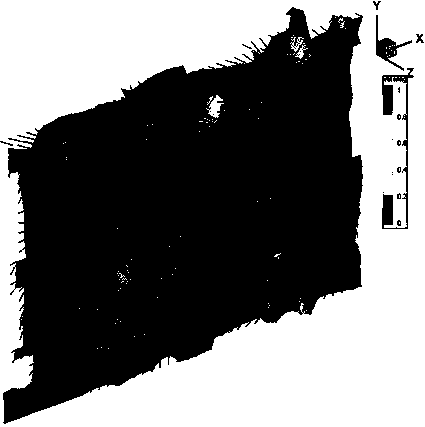
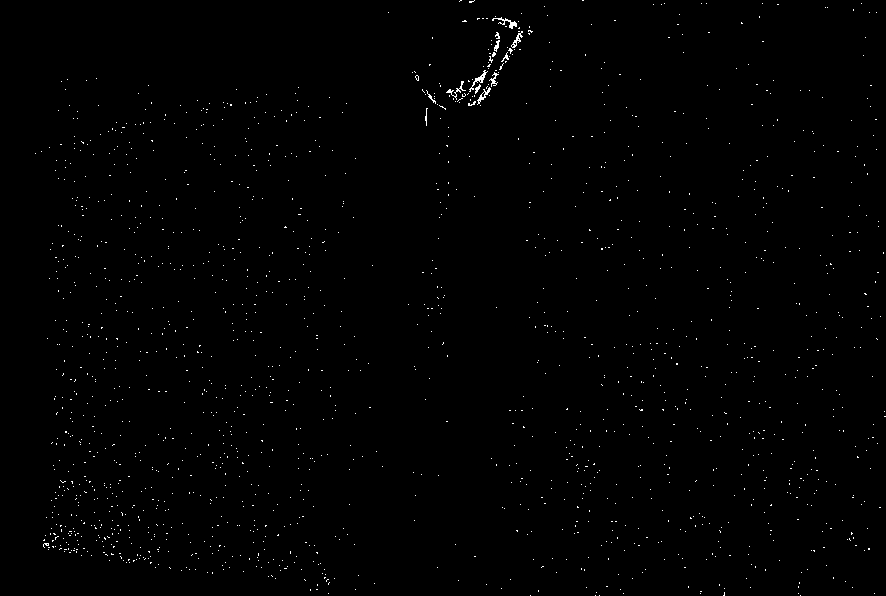
The light intensity of the laser sheet light source will attenuate quickly when it is injected into the water-sand two-phase flow, resulting in a large difference in the brightness of the measurement plane; at the same time, the light transmittance in muddy water is poor, and the reflected light attenuates quickly after the measurement plane is illuminated. The particle image of the effect is very poor (such as figure 1 , 2 shown)
Therefore, usually only the low-density mixed phase can use PIV technology to measure the internal flow field. For hyperpycnal flow with high sand content and muddy water, only the flow field of clear water around the hyperpycnal flow can be observed when using PIV technology. The real-time planar flow field measurement in muddy water is still difficult. Very difficult
Therefore, the application of PIV technology in water-sand two-phase flow has been greatly limited.
[0006] At present, there is no relatively successful test method using PIV technology to observe the internal flow field of water-sand two-phase flow at home and abroad.

Method used


Image

  • Method using particle image velocimetry technology to measure sediment two-phase flow field
  • Method using particle image velocimetry technology to measure sediment two-phase flow field
  • Method using particle image velocimetry technology to measure sediment two-phase flow field

Examples


Embodiment 1

[0019] Embodiment 1: Carry out particle analysis on the silt in the water-sand two-phase flow to be measured in the test, and prepare replacement glass beads according to the gradation of the silt; carry out a sedimentation test on the test water-sand two-phase flow, and observe the density change Process curve; use replacement glass beads and water to prepare a mixed solution according to the mass concentration of the test water-sand two-phase flow, and conduct the above-mentioned sedimentation test to observe the density change process curve of the mixed solution; if the density change process curves of the two groups are similar, it is considered that the mud The sedimentation process of sand and glass beads of the same gradation is similar, and the two-phase flow test can be carried out with replacement glass beads and water; Test fluid (a solution of sugar in water is recommended as an alternative fluid).

[0020] Place the calibration plate in the test fluid, run the...


PUM


Abstract

The invention discloses a method using particle image velocimetry technology (PIV) to measure sediment two-phase flow field, and mainly used for inner flow velocity field measurement in a sediment two-phase flow fluid test; the method uses glass beads of high transparency to replace sediment particles of opacity or poor transparency; the glass beads mix with water or other liquid having similar refractive index with glass and excellent transparency so as to form a solid-fluid two-phase flow; the mixed solid-liquid two-phase flow is used for the fluid test, and the PIV technology is used for measuring the inner flow velocity field. The beneficial effects are that shooting image clearness of a PIV system can be improved in the sediment two-phase flow test, thus enhancing measuring precision, and realizing real time measurement of sediment two-phase flow inner flow velocity field with high concentration.

Description

[0001] technical field [0002] The invention belongs to the field of fluid testing and relates to a method for measuring fluid velocity field using particle image velocimetry (PIV), in particular to a method for measuring the internal flow velocity field of water-sand two-phase flow. Background technique [0003] Particle Image Velocimetry (hereinafter referred to as PIV) is a transient, full flow field, non-contact fluid image velocimetry technology developed in the late 1970s. The basic principle is: use a laser sheet light source to illuminate the plane to be observed in the fluid, and then take two images of the observation plane continuously by a high-speed camera. The position change of the tracer particles) and the shooting interval time are obtained to obtain the instantaneous flow velocity field of the observation plane (the default is that the tiny particles are consistent with the fluid motion). [0004] Two-phase flow composed of solid and liquid is a kind ...

Claims


Application Information

Patent Timeline
Patent Type & Authority Applications(China)
IPC IPC(8): G01M10/00
Inventor 陈铂
Owner CHANGSHA UNIVERSITY OF SCIENCE AND TECHNOLOGY
Why Eureka
Try Eureka