Booster-flyback convertor of built-in switch coupling inductance

A technology of flyback converters and coupled inductors, applied in electrical components, output power conversion devices, etc., can solve the voltage peak of the transformer winding power switch tube, increase the current stress of the switch tube and diode, and turn on and off the switch tube Large loss and other problems, to achieve the effect of less power loss, reduced turn-on and turn-off losses, and reasonable structural design

Inactive Publication Date: 2014-12-24
QINGDAO TECHNOLOGICAL UNIVERSITY
View PDF12 Cites 8 Cited by
  • Summary
  • Abstract
  • Description
  • Claims
  • Application Information

AI Technical Summary

Problems solved by technology

The traditional boost converter achieves higher voltage gain by increasing the duty cycle, but when the output voltage is higher, the voltage stress on the power switch tube is greater, and the output diode has a reverse recovery problem, which will reduce the converter's output voltage. efficiency, so the application of boost converters is limited
In the existing technology, the flyback converter generally adopts the flyback transformer technology to achieve higher voltage gain, but the leakage inductance of the transformer winding of this technology is likely to cause voltage spikes on the power switch tube, and the switch tube conduction and turn-off losses Larger, resulting in lower converter efficiency, therefore, this technology is generally only used in step-down small and medium power applications
The integrated boost-flyback converter in the existing conventional technology combines the flyback transformer and the boost converter to achieve a high boost ratio, but this method needs to achieve a larger The inductance and leakage inductance of the primary side and secondary side of the flyback transformer will double, which will reduce the efficiency of the converter; at the same time, the primary side of the flyback transformer will bear a higher current gain, thereby increasing the switching tube and diode current stress, resulting in an increase in the cost of the converter

Method used


Image

  • Booster-flyback convertor of built-in switch coupling inductance
  • Booster-flyback convertor of built-in switch coupling inductance
  • Booster-flyback convertor of built-in switch coupling inductance

Examples


Embodiment

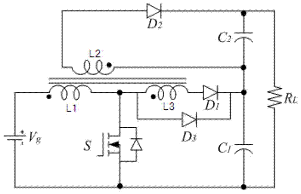
[0011] The schematic diagram of the electrical principle of this embodiment is as figure 1 As shown, the boost-flyback converter with built-in switch coupling inductor consists of a boost module and a flyback module; the boost module includes a DC power supply V g , the first winding L 1 , the third winding L 3 , power switch tube S, freewheeling diode D 1 , clamping diode D 3 and the first output capacitor C 1 ; DC power supply V g The positive terminal and the first winding L 1 The terminal of the same name is connected, the DC power supply V g The negative terminal is connected to the source of the power switch tube S, and the first output capacitor C 1 of the negative terminal and the load R L One end is connected; the first winding L 1 The opposite terminal of the power switch tube S and the drain of the clamping diode D 3 anode and tertiary winding L 3 One end is connected; the third winding L 3 The other end of the freewheeling diode D 1 The anode is connec...


PUM


Abstract

The invention belongs to the technique field of power electron and relates to a booster-flyback convertor of built-in switch coupling inductance, and the booster-flyback convertor of built-in switch coupling inductance comprises a boosting module and a flyback module; the direct current power positive pole end of the boosting module is connected to the first winding dotted terminal, and the negative pole end is connected to the source of the power switch tube, the negative pole end of the output capacitor and one end of the load, the first winding synonym terminal is connected to the drain of the power switch tube, anode of catching diode and one end of the third winding, the other end of the third winding is connected to the anode of fly-wheel diode, the cathode of the fly-wheel diode is connected to the cathode of the catching diode, the positive pole of the output capacitor and flyback module; the second winding dotted terminal of flyback module is connected to the negative pole of the output capacitor and the boosting module, the synonym terminal is connected to the anode of the fly-wheel diode, the cathode of the fly-wheel diode is connected to the positive pole of the output capacitor and the other end of the load; the circuit structure is reasonable in design, safe and reliable in use, low in cost and friendly in environment with great utilization potentiality.

Description

Technical field: [0001] The invention belongs to the technical field of power electronics, and relates to a DC-DC converter, in particular to a boost-flyback converter with a built-in switch coupling inductor. Background technique: [0002] At present, the lack of non-renewable energy seriously restricts economic development, so higher requirements are put forward for the utilization of electric energy. The traditional boost converter achieves higher voltage gain by increasing the duty cycle, but when the output voltage is higher, the voltage stress on the power switch tube is greater, and the output diode has a reverse recovery problem, which will reduce the converter's output voltage. Efficiency, so the application of the boost converter is limited. In the existing technology, the flyback converter generally adopts the flyback transformer technology to achieve higher voltage gain, but the leakage inductance of the transformer winding of this technology is likely to cause ...

Claims


Application Information

Patent Timeline
Patent Type & Authority Applications(China)
IPC IPC(8): H02M1/36
Inventor 丁新平王天兵王伯荣苑红
Owner QINGDAO TECHNOLOGICAL UNIVERSITY
Why Eureka
Try Eureka