Novel double-bootstrap coupling inductor quasi-Z-source inverter and control method

A technology of coupled inductors and source inverters, applied to electrical components, AC power input to DC power output, output power conversion devices, etc., can solve the problem of increased diode current stress, reduced inverter efficiency, and increased circuit complexity In order to achieve the effects of reducing voltage stress, safe use, and reasonable design of the overall structure of the circuit

Pending Publication Date: 2021-11-19
QINGDAO TECHNOLOGICAL UNIVERSITY
View PDF4 Cites 0 Cited by
  • Summary
  • Abstract
  • Description
  • Claims
  • Application Information

AI Technical Summary

Problems solved by technology

However, the introduction of coupled inductance also increases the current stress of the diode in the non-through state, increases the loss of the entire branch circuit, and reduces the efficiency of the inverter
In the document "Ahmed H F, Cha H, Kim S H and Kim H G.Switched-coupled-inductorquasi-Z-source inverter[J].IEEE Transactions on Power Electronics,2016,31(2):1241-1254", through the The combination of the SC structure and the three windings constitutes a switched-coupled-inductor quasi-Z-Source Inverter (SCL-qZSI). However, the introduction of the three windings greatly improves the circuit performance. Boost capability, on the other hand, also increases the complexity of the circuit, increases losses, and reduces the efficiency of the inverter
The document "Sharifi S and Monfared M. Modified series and tapped switched-coupled-inductors quasi-Z-source networks [J]. IEEE Transactions on Industrial Electronics, 2019, 66(8): 5970-5978" proposed an improved series switch coupled inductor and Tapped switch coupled inductor two new quasi-Z source inverters (Modified Series Switched-Coupled-Inductorquasi-Z-Source Inverter, MSSCL-qZSI; Modified Tapped Switched-Coupled-Inductorquasi-Z-Source Inverter, MTSCL-qZSI), but Same as SCL, with added system complexity

Method used


Image

  • Novel double-bootstrap coupling inductor quasi-Z-source inverter and control method
  • Novel double-bootstrap coupling inductor quasi-Z-source inverter and control method
  • Novel double-bootstrap coupling inductor quasi-Z-source inverter and control method

Examples


Embodiment 1

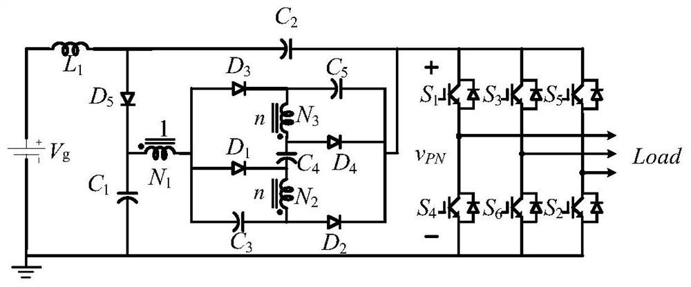
[0020] The structure of the new double bootstrap coupled inductor quasi-Z source inverter described in this embodiment is as follows: figure 1 said, by the DC power supply V g , a set of coupled inductors (the first winding L N1 , the second L N2 , the third L N3 ), power switch tube S 1 ~S 6 , the first inductance L 1 , the first diode D 1 , the second diode D 2 , the third diode D 3 , the fourth diode D 4 , the fifth diode D 5 , the first capacitance C 1 , the second capacitance C 2 , the third capacitor C 3 , the fourth capacitor C 4 , the fifth capacitor C 5 and load R Load Composition; the first winding L N1, the second winding L N2 , the third winding L N3 Coupled with each other, and the turns ratio is 1:n:n. The first winding L of the hybrid dual bootstrap switch coupled inductor unit N1 Different terminal and the first and third diodes D 1 、D 3 The anode of the third capacitor C 3 connected to the negative pole; the second winding L N2 The dott...

Embodiment 2

[0030] This embodiment uses the inverter described in Embodiment 1. When the output voltage is required to be converted to 10 times the input voltage, if the output voltage expression according to the existing basic topology is:

[0031]

[0032] To meet the requirements of the output voltage, the duty cycle value D is 0.91. At this time, the switch tube is already in the limit state, which affects the working efficiency and will cause great damage to related devices;

[0033] When according to the gain expression of the inverter described in this embodiment:

[0034]

[0035] When the straight-through duty ratio is 0.1, the turn ratio n=0.54 between the coupling windings can meet the output requirement. Therefore, compared with the original basic topology, this embodiment can realize the output of a wide range of voltages, avoid the occurrence of the limit duty cycle, effectively improve the working efficiency of the topology, and reduce the loss of each device.


PUM


Abstract

The invention belongs to the technical field of DC-AC conversion equipment, and relates to a novel dual-bootstrap coupling inductor quasi-Z-source inverter and a control method thereof. A switch module controls whether a DC power supply and a hybrid dual-bootstrap switch coupling inductor unit provide or stop providing energy for a load through on or off switching; and the hybrid dual-bootstrap switch coupling inductor unit is provided with mutually coupled windings, boost conversion of output voltage to DC power supply voltage is realized by changing the turn ratio of the coupling windings, two-degree-of-freedom adjustment of duty ratio and turn ratio is realized, the number of the coupling windings and the size of a single winding are reduced, and the conversion efficiency of the converter is improved.

Description

technical field [0001] The invention belongs to the technical field of DC-AC conversion equipment, and relates to a novel double bootstrap coupled inductance quasi-Z source inverter and a control method. Background technique [0002] Today, the environmental pollution caused by fossil energy is increasing day by day, which has prompted the rapid development of renewable energy. As one of the clean renewable energy sources, solar energy has considerable development prospects. The traditional photovoltaic power generation system uses the DC / AD inverter to output the output voltage of multi-level photovoltaic cells to the grid, but the multi-level structure has high production costs and failure rates. On this basis, a DC / DC boost converter is added between the photovoltaic cell and the grid to complete the boost first, and then perform the inversion, but this DC / DC-DC / AC structure will lead to a complex system structure and low working efficiency. Inferior question. [0003]...

Claims


Application Information

Patent Timeline
Patent Type & Authority Applications(China)
IPC IPC(8): H02M7/5387H02M7/5395H02M1/00
CPCH02M7/53871H02M7/5395H02M1/00
Inventor 张民韦正怡周明珠王凤莲曹益畅赵振伟袁成功丁新平
Owner QINGDAO TECHNOLOGICAL UNIVERSITY
Why Eureka
Try Eureka