Single-electrode friction nanogenerator and generating method and self-driven tracking device
A nanogenerator and generator technology, applied in the directions of triboelectric generators, transportation and packaging, chemical instruments and methods, etc., to achieve the effects of simplifying circuit connections, expanding application scope, and reducing production costs
- Summary
- Abstract
- Description
- Claims
- Application Information
AI Technical Summary
Problems solved by technology
Method used
Image
Examples
Embodiment 1
[0140] Example 1: Preparation of single-electrode friction nanogenerator
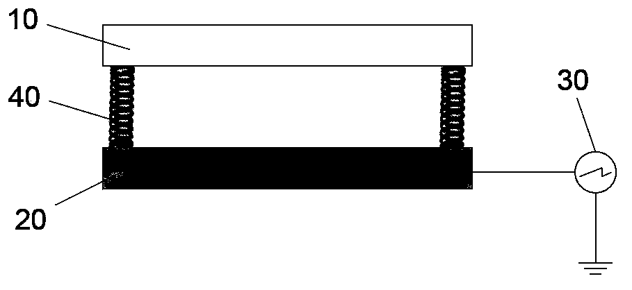
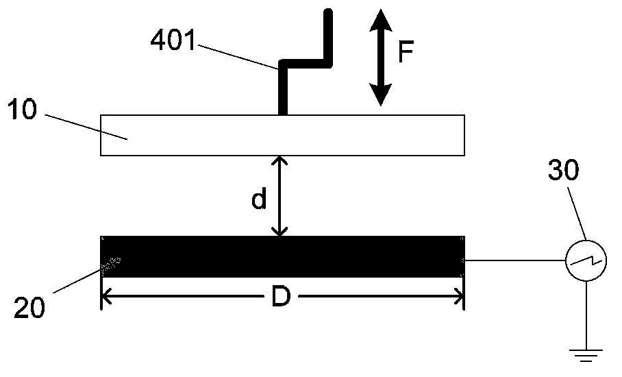
[0141] A plexiglass plate with a length of 3 cm × a width of 3 cm × a thickness of 1.59 mm was used as the second supporting element, and a piece of Al foil was used to completely cover the entire plexiglass plate. A piece of nylon film with a length of 7 cm × a width of 3 cm × a thickness of 25 μm and a piece of polyimide with a length of 7 cm × a width of 3 cm × a thickness of 127 μm are bonded together with adhesive tape. The surface of the nylon faces the Al foil, and its two ends are fixed on the plexiglass with tape. Connect the Al foil with a copper wire and connect it to a resistor, and the other end of the resistor is grounded. Because the polyimide film has good elasticity, it can ensure that the nylon film and the Al foil are completely separated without pressure. During compression, the two films can touch together. Apply an external force to the flexible outer membrane of the generator, suc...
Embodiment 2
[0142] Example 2: Preparation of a single-electrode friction generator set
[0143] A plexiglass plate with a length of 10 cm × a width of 10 cm × a thickness of 1.59 mm was cut by a laser as the second supporting element, and two 2 cm × 2 cm × 0.5 mm Cu films were prepared on it. Evenly bond four 1mm thick high-elastic sponge blocks around each piece of Cu film as elastic parts, and take two 3cm×3cm×1mm polyester sheets as the friction layer, respectively, with the two pieces on the second supporting element The copper film is facing each other, and the other end of the high elastic sponge is adhered to its lower surface to form a similar Picture 9 The structure shown. Each Cu film is connected by a wire and a resistor with one end grounded to form a generator set with 2 generators. Its structure is Figure 18 The illustrated embodiment is similar. Due to the function of the highly elastic sponge, it can be ensured that the polyester sheet and the Cu film are completely separa...
Embodiment 3
[0145] Example 3: Preparation of single-electrode friction generator tracking system
[0146] According to the method of Example 1, 16 friction generators of the same size were fabricated and arranged in a 4×4 matrix. The circuit connection of the entire generator set is as follows Picture 20 Shown. When an object moves in the tracking system, the contact between the object and the friction generator will cause the generator to compress, thereby outputting an external electrical signal. Through the collection of these signals, the detection of the moving path of the object can be realized. The system directly uses the friction generator as the trigger sensor, does not require external power supply, can effectively save energy, and can work stably for a long time. When we compress a generator, the data image obtained can clearly show that it is the seventh generator ( Figure 21 ).
PUM
| Property | Measurement | Unit |
|---|---|---|
| Thickness | aaaaa | aaaaa |
| Thickness | aaaaa | aaaaa |
Abstract
Description
Claims
Application Information
 - R&D
- Intellectual Property
- Life Sciences
- Materials
- Tech Scout
- Unparalleled Data Quality
- Higher Quality Content
- 60% Fewer Hallucinations
Browse by: Latest US Patents, China's latest patents, Technical Efficacy Thesaurus, Application Domain, Technology Topic, Popular Technical Reports.
© 2025 PatSnap. All rights reserved.Legal|Privacy policy|Modern Slavery Act Transparency Statement|Sitemap|About US| Contact US: help@patsnap.com


