Novel visual intelligent super-fluid cast-in-place concrete pile device and construction method

A concrete and superfluid technology, applied in earth-moving drilling, drilling equipment and methods, sheet pile walls, etc., can solve problems such as high cost, poor pile quality, waste of concrete, etc., and achieve easy understanding of technology and shorten construction. The effect of time and vibration speed

Inactive Publication Date: 2014-12-31
SHANGHAI CHENGDI CONSTR +1
View PDF9 Cites 8 Cited by
  • Summary
  • Abstract
  • Description
  • Claims
  • Application Information

AI Technical Summary

Problems solved by technology

At present, the construction of concrete pouring piles has the disadvantages of wasting concrete and high cost. At the same time, the construction period also needs to be improved. The degree of intelligence of construction machinery is not high. In many cases, the addition of materials is based on the experience of the on-site staff, which cannot be carried out well. monitoring management
[0007] The original method of pressure grouting piles is not equipped with a visual intelligent system, the quality of the pile body is poor, and the quality of pile formation is uncontrollable

Method used


Image

  • Novel visual intelligent super-fluid cast-in-place concrete pile device and construction method
  • Novel visual intelligent super-fluid cast-in-place concrete pile device and construction method
  • Novel visual intelligent super-fluid cast-in-place concrete pile device and construction method

Examples


Embodiment Construction

[0023] The present invention will be described in detail below in conjunction with the accompanying drawings and specific embodiments.

[0024] Example:

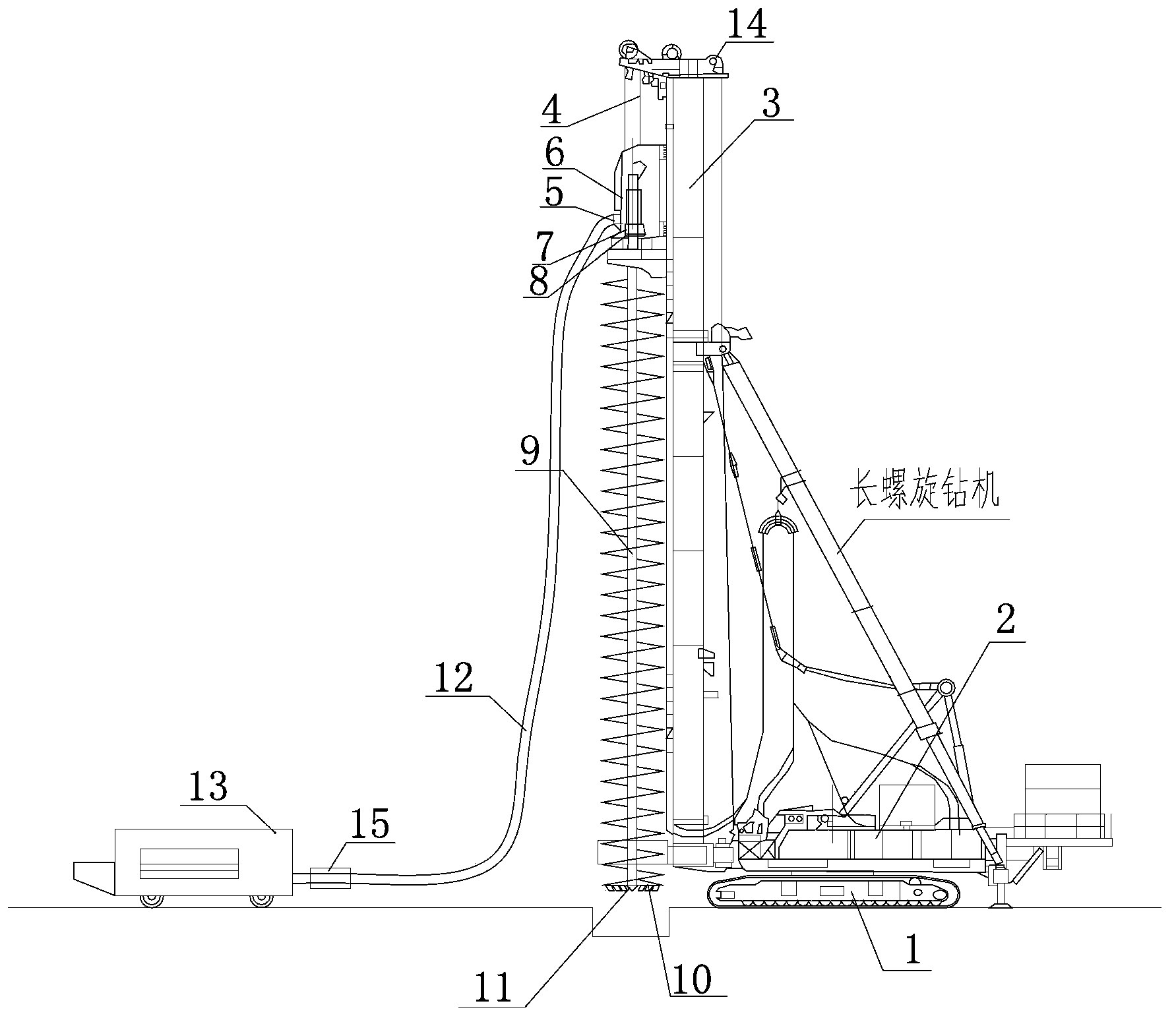
[0025] Such as figure 1 As shown, a new type of visual intelligent superfluid concrete pouring pile device, the device includes walking and crawler main engine 1, winch 2, guide rod 3, steel wire rope 4, feed port 5, power head 6, gearbox 7, Reducer 8, auger rod 9, drill bit 10, discharge port 11, pump truck conduit 12, concrete pump truck 13, flow meter 14, depth sensor 15, the hoist 2 and guide rod 3 are fixed on the main machine 1 Above, the power head 6 is connected to the top pulley of the guide rod through the wire rope 4, and the wire rope 4 drives the power head 6 to go up and down, and the power head 6 is connected to the auger rod 9 through the gearbox 7 and the reducer 8 in turn, 9 The lower end is connected to the drill bit 10, and the drill bit 10 is provided with a discharge port 11. The discharge port 11 is ...


PUM


Abstract

The invention relates to a novel visual intelligent super-fluid cast-in-place concrete pile device and a construction method. The novel visual intelligent super-fluid cast-in-place concrete pile device comprises a walking and crawler type main machine, a winding machine, a guide rod, a steel wire rope, a feed inlet, a power head, a gearbox, a speed reducer, a spiral drill rod, a drill bit, a feed outlet, a pump truck guide pipe, a concrete pump truck, a flow meter and a depth sensor, wherein the winding machine and the guide rod are fixedly arranged on the main machine, the power head is connected with a pulley arranged at the top end of the guide rod through the steel wire rope, the steel wire rope drives the power head to ascend and descend, the power head is sequentially connected with the spiral drill rod through the gearbox and the speed reducer, the lower end of the spiral drill rod is connected with the drill bit, the feed outlet is formed in the drill bit and is provided with an iron sheet, the iron sheet is fixed by a bolt, the concrete pump truck is connected with the feed inlet through the pump truck guide pipe, and the pump truck guide pipe is provided with the flow meter. The invention also provides the construction method of a novel visual intelligent super-fluid cast-in-place concrete pile. The construction method comprises the steps of firstly, drilling to a design depth by a long spiral drilling machine; then, forwards rotating or directly lifting the drill rod; continuously infusing super-fluid concrete in a hole through a drill bit valve while pulling out the drill rod; finally, inserting a steel reinforcement cage after pulling out the drill rod. Compared with the prior art, the novel visual intelligent super-fluid cast-in-place concrete pile device and the construction method, provided by the invention, have the advantages that no noise or vibration is generated, a soil compaction performance is not generated, intelligentization is realized, the quality is ensured, the cost is reduced, the construction period is shortened, and the like.

Description

technical field [0001] The invention relates to a novel visualized intelligent superfluid concrete pouring pile device and a construction method, which are mainly used in foundation pit enclosure retaining soil and main structure vertical stress in civil and industrial infrastructure construction. Background technique [0002] At present, the conventional concrete cast-in-place pile construction methods include dry-work bored piles, mud retaining wall bored piles, casing bored piles, and blast-expanded bored piles, etc. [0003] The construction process of cast-in-situ piles in dry operation: site cleaning → measuring and setting out the pile position → placing the pile machine → drilling and taking soil to form the hole → removing the sediment at the bottom of the hole → inspection and acceptance of the hole quality → hanging and placing the reinforcement cage → pouring Concrete in the hole. [0004] The cast-in-situ piles with mud arm guards use mud to protect the wall. W...

Claims


Application Information

Patent Timeline
Patent Type & Authority Applications(China)
IPC IPC(8): E02D5/34E02D15/04E21B3/00
Inventor 谢晓东周玉石谢益飞赵伟明黄立伟鲍国强汤武张群邢克伦施问知
Owner SHANGHAI CHENGDI CONSTR
Why Eureka
Try Eureka