Energy-saving chemical gypsum drying and calcining system

A chemical gypsum and energy-saving technology, which is applied in the field of energy-saving chemical gypsum drying and calcining systems, can solve the problems of unstable gypsum product quality, affecting the quality of downstream products, and difficulty in improving the quality, so as to delay the kiln discharge time and prolong the retention time. time, the effect of reducing the temperature of the kiln

Active Publication Date: 2015-01-07
上海鹊之家建筑科技有限公司
View PDF5 Cites 11 Cited by
  • Summary
  • Abstract
  • Description
  • Claims
  • Application Information

AI Technical Summary

Problems solved by technology

At present, the drying and calcination system used for chemical gypsum is difficult to control or the control is not accurate enough, but the chemical gypsum is very sensitive to temperature during the drying and calcination process, which changes a lot and directly affects the phase transition of gypsum. The quality of the gypsum products produced by drying and calcining is very unstable, and the quality is difficult to improve, which directly affects the quality of downstream products; at the same time, in the existing drying and calcining system, the flow of hot air into the furnace is advection, and Airflow always flows towards open areas and places with less wind resistance (see Image 6 ), most of the hot air flows away from the open area (that is, area A in the figure), taking away a large amount of heat, resulting in a higher temperature of the air flow out of the furnace and a lower heat utilization rate; The resistance of the material, the air flow is less, and the hot air flows away without sufficient heat exchange with the cold material. The heat utilization rate is low, resulting in waste and high energy consumption.

Method used


Image

  • Energy-saving chemical gypsum drying and calcining system
  • Energy-saving chemical gypsum drying and calcining system
  • Energy-saving chemical gypsum drying and calcining system

Examples


Embodiment Construction

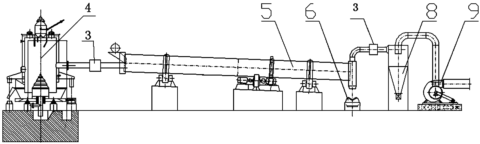
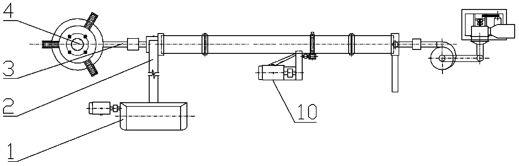
[0014] Such as Figure 1-2 As shown, an energy-saving chemical gypsum drying and calcining system includes a hot blast furnace 4, a drum drying and calcining kiln 5 connected to the hot blast furnace, and the drum drying and calcining kiln is supported on a rolling support device through a tyre. And driven by the kiln body rotary frequency conversion motor 10, the raw meal input machine 2 installed at the front end of the drum drying and calcining kiln and the raw material processing machine 1 connected to the upper end of the raw material input machine (the raw material processing machine is equipped with material scattering And homogenization device), the discharge conveyor 6, the dust collector 8, and the induced draft fan 9 are arranged in sequence at the rear end of the drum drying and calcining kiln. The first and second heat flow controllers 3 are provided between the drying and calcining kiln 5 and the hot air furnace 4 and between the drum drying and calcining kiln 5 a...


PUM


Abstract

The invention discloses an energy-saving chemical gypsum drying and calcining system which comprises a hot-blast furnace and a cylindrical drying and calcining kiln communicated with the hot-blast furnace, wherein the cylindrical drying and calcining kiln is supported on a rolling support device through a wheel belt and driven by a kiln revolution variable-frequency motor; a green material conveyer arranged at the front end of the cylindrical drying and calcining kiln and a raw material treatment machine connected to the upper end of the green material conveyer are sequentially arranged on a delivery conveyer, a dust remover and a draught fan at the back end of the cylindrical drying and calcining kiln; and a hot flow controller is arranged between the hot-blast furnace and cylindrical drying and calcining kiln communicated with the hot-blast furnace and between the cylindrical drying and calcining kiln and dust remover. Hot air flow can be guided to flow in a spiral mode, so that the hot air flow can generate a tornado-flow heat transfer effect in the kiln and have a quick-sweeping heat exchange effect, thereby postponing the hot flow discharge time, lowering the discharge temperature of the air flow, saving the energy and greatly enhancing the heat exchange efficiency.

Description

Technical field [0001] The invention relates to a gypsum drying and calcination system, in particular to an energy-saving chemical gypsum drying and calcination system. Background technique [0002] Chemical gypsum refers to the main component of calcium sulfate in industrial by-products or emissions, collectively referred to as chemical gypsum. There are mainly desulfurized gypsum, phosphogypsum, titanium gypsum, nickel gypsum, fluorogypsum, etc., which are all industrial wastes. The annual discharge amounts to hundreds of millions of tons. If it is not developed and utilized in time, it will cause serious pollution to the soil, water sources, and air, and damage the ecological environment and living conditions of human beings. Therefore, the significance of the development and utilization of chemical gypsum resources is not only to replace natural gypsum, but also to alleviate the emission pollution of solid waste residues and reduce the expensive landfill costs of solid waste...

Claims


Application Information

Patent Timeline
Patent Type & Authority Applications(China)
IPC IPC(8): C04B11/028
Inventor 韩永发
Owner 上海鹊之家建筑科技有限公司
Why Eureka
Try Eureka