A hydraulic natural gas vehicle refueling substation

A technology of hydraulic natural gas and gas filling sub-stations, which is applied to equipment loaded into pressure vessels, gas/liquid distribution and storage, pipeline systems, etc. Problems such as malfunction of operation and high residual pressure of equipment can achieve the effect of small footprint, high safety and high air intake rate

Active Publication Date: 2016-10-19
XINXING ENERGY EQUIP
View PDF6 Cites 0 Cited by
  • Summary
  • Abstract
  • Description
  • Claims
  • Application Information

AI Technical Summary

Problems solved by technology

When the natural gas cylinder trailer is transferred to the sub-station in the city, the hydraulic natural gas vehicle refueling sub-station will continuously replenish the pressure through the hydraulic oil pump of the equipment, so as to maintain the working pressure of the natural gas in the sub-station trailer and continuously replenish it to In the user's equipment, after the gas in one of the gas cylinders is discharged, the oil needs to be returned and the next oil pumping action is repeated. On the one hand, when the oil return is about to end, the oil and gas mixture will enter the fuel tank and pass through the drain pipe of the fuel tank The natural gas is wasted through release, which directly affects the gas consumption. On the other hand, when the equipment returns to oil, if the end lags behind, there will be outward fuel injection or the explosion-proof device of the fuel tank will be opened. If the end is advanced, the oil return will be unclean, and the equipment will Problems such as excessive residual pressure; these will cause malfunctions in the operation of the equipment, reduce safety, and the problems of oil return with gas and dirty oil have always affected the normal and continuous operation of the equipment

Method used


Image

  • A hydraulic natural gas vehicle refueling substation

Examples


Embodiment Construction

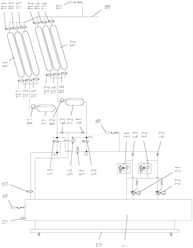
[0008] Such as figure 1 As shown, fuel tank 1, first and second high-pressure oil pumps 2.1 and 2.2, first and second pilot solenoid valves 3.1 and 3.2, first and second one-way valves 4.1 and 4.2, first and fourth pneumatic ball valves 5.1 , 5.2, 5.3, 5.4, the first and second manual ball valves 6.1 and 6.2, the first and second buffer accumulators 7.1 and 7.2, the first and second liquid level transmitters 8.1 and 8.2, the first and second The second gas cylinder group 9.1, 9.2, the first - the sixth oil circuit pneumatic ball valve 10.1, 10.2, 10.3, 10.4, 10.5, 10.6, the first - the sixth gas circuit pneumatic ball valve 11.1, 11.2, 11.3, 11.4, 11.5, 11.6, fuel tank magnetic float flap liquid level gauge 12, fire arresting release cap 13, oil return detection pressure transmitter 14, electromagnetic stop valve 15, oil pressure transmitter 16, air pressure transmitter 17, gas sales interface 18.

[0009] On the fuel tank 1, a fuel tank magnetic float flap liquid level gauge...


PUM


Abstract

The invention relates to a gas filling substation for a hydraulic natural gas vehicle. The oil tank is fixed with a magnetic float flap liquid level gauge, a fire arresting release cap and an oil return detection pressure transmitter; the oil inlet end of the pump oil system is in communication with the oil tank, and the oil outlet end of the oil pump system is connected with the solenoid valve The a interface of the bridge is sealed and communicated, and the solenoid valve bridge is composed of the first ‑ fourth pneumatic ball valve, forming a bridge oil circuit with the same principle as the bridge rectifier circuit composed of four diodes; the b interface of the solenoid valve bridge passes through the first The second buffer accumulator, the second, fourth and sixth oil circuit pneumatic ball valves are in sealing communication with the oil inlet port of the second gas cylinder group, and the gas outlet port of the second gas cylinder group is pneumatically operated through the second, fourth and sixth gas circuit The ball valve is in sealing communication with the gas sales interface. Solve the problem that the oil return is not clean at the early cut-off of the system and the natural gas is released into the atmosphere after the late cut-off.

Description

technical field [0001] The invention belongs to a vehicle gas filling substation, in particular to a vehicle gas filling substation of hydraulic natural gas. Background technique [0002] At present, with the national requirements for energy saving, consumption reduction, and environmental pollution reduction, the construction of CNG hydraulic natural gas vehicle filling stations has become an inevitable trend to reduce smog and develop clean energy. Natural gas is a colorless, odorless, non-toxic, high-calorific value, stable combustion, clean and environmentally friendly high-quality energy. Compressed natural gas (CNG), as an alternative fuel for urban buses, taxis, and short-distance transportation, has many advantages such as low price and no pollution, and has been used more and more in the country. When the natural gas cylinder trailer is transferred to the sub-station in the city, the hydraulic natural gas vehicle refueling sub-station will continuously replenish th...

Claims


Application Information

Patent Timeline
Patent Type & Authority Patents(China)
IPC IPC(8): F17C5/00F17D1/04F17D3/01
Inventor 汪宇李建韦武常生姚振龙胡永卫陈英嘉秦瑞
Owner XINXING ENERGY EQUIP
Why Eureka
Try Eureka