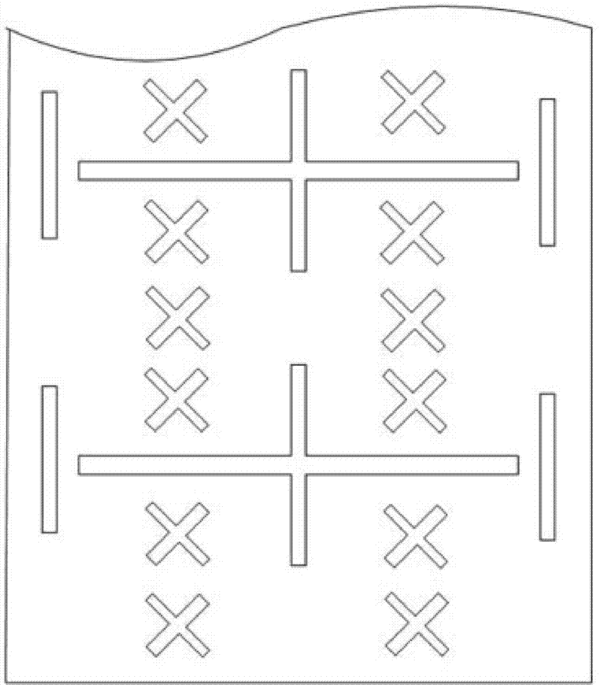
Ultra-wide frequency band multi-band array antenna

An array antenna and ultra-wideband technology, which is applied in the field of ultra-wideband multi-band array antennas, can solve the problems of increasing cost, production difficulty, and reducing antenna gain, so as to reduce operation and maintenance costs, reduce the number of antennas, and have a simple and compact structure Effect

Active Publication Date: 2015-01-07
GUANGDONG BROADRADIO COMM TECH
7 Cites 31 Cited by

AI-Extracted Technical Summary

Problems solved by technology

This structure not only increases the cost and production difficulty,...

Method used

As an improvement, two parasitic vibrators 103 are also provided on both sides of the low-frequency radiation unit 1, and the two parasitic vibrators 103 are respectively arranged on both sides of the low-frequency vibrator 1, and are fed by the radiation arm coupling of the low-frequency vibrator electricity to adjust the vertically polarized component of the far-field radiation and improve beam convergence.
As shown in Figure 5 and Figure 6, the embodiment of the present invention is improved on the basis of Embodiment 1, specifically, the end of the low-frequency vibrator also has a bending section, and the bending section is at the end of the low-frequency vibrator The end is bent left and right along the horizontal direction or set up and down along the vertical direction. In the embodiment of the present invention, the bending section is bent toward both sides of the low-frequency radiation unit 1, the extension direction of the bending section is perpendicular to the extension direction of the low-frequency array, and the bending section is located between two adjacent high-frequency radiation units 2 between. This structure prolongs the length of the low-frequency vibrator, enhances the radiation characteristics of the low-frequency radiation unit 1, and simultaneously av...

Abstract

The invention relates to an ultra-wide frequency band multi-band array antenna which comprises a metal reflection plate, a low-frequency radiation unit and a high-frequency radiation unit. The low-frequency radiation unit and the high-frequency radiation unit are mounted on the metal reflection plate, the low-frequency radiation unit works on a low-frequency band, and the high-frequency radiation unit works on a high-frequency band. The low-frequency radiation unit comprises two low-frequency oscillators which are both in +/-45-degree polarization and are mounted in a mutually orthogonal mode, the two low-frequency oscillators are connected with a feed network, and a +/-45-degree polarization far field radiation directional diagram is generated; the high-frequency radiation unit comprises two high-frequency oscillators which are both in +/-45-degree polarization and are mounted in a mutually orthogonal mode. The multi-band array antenna is capable of covering a 694-960 MHz ultra-wide frequency band and a 1710-2690 MHz ultra-wide frequency band and is simple in structure so as to be compatible with all frequency bands of a current mobile communication network.

Application Domain

Technology Topic

Image

  • Ultra-wide frequency band multi-band array antenna
  • Ultra-wide frequency band multi-band array antenna
  • Ultra-wide frequency band multi-band array antenna

Examples

  • Experimental program(5)

Example Embodiment

[0031] Example one
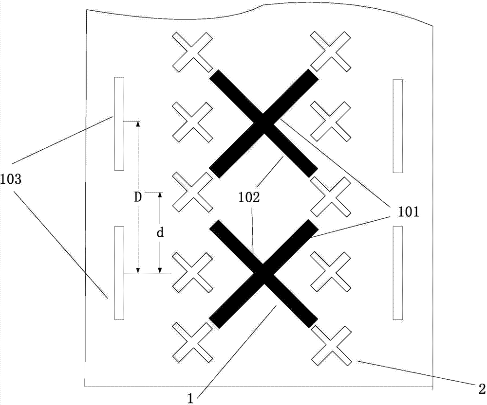
[0032] Such as Figure 2 to Figure 4 As shown, an ultra-wideband three-band array antenna provided by an embodiment of the present invention includes a metal reflector, and a low frequency radiating unit 1 that works in a lower frequency band and a high frequency radiation unit 1 that works in a higher frequency band installed on the metal reflector. Frequency radiation unit 2. Preferably, the low-frequency radiation unit 1 operates in a frequency range of 694-960 MHz, and the high-frequency radiation unit 2 operates in a frequency range of 1710-2690 MHz.
[0033] The low-frequency radiating unit 1 includes two low-frequency vibrators which are polarized at ±45 degrees and installed orthogonally to each other, which are the positive-polarized low-frequency vibrator 101 and the negative-polarized low-frequency vibrator 102 respectively. The two low-frequency vibrators are connected to the feed network to generate ± 45-degree polarized far-field radiation pattern. The centers of the multiple low-frequency radiation units 1 are arranged at equal intervals along the first reference line to form a low-frequency array.
[0034] The high-frequency radiation unit 2 includes two high-frequency vibrators that are polarized at ±45 degrees and are installed orthogonally to each other, which are an anode-polarized high-frequency vibrator and a negative-polarized high-frequency vibrator. Wherein, the extension directions of the co-polarized vibrator in the high-frequency radiation unit 2 and the low-frequency radiation unit 1 are parallel or coincide, that is, the extension directions of the anodized low-frequency vibrator 101 and the anodized high-frequency vibrator are parallel or coincide, and the negative-polarized low-frequency vibrator 102 and The extension directions of the negatively polarized high-frequency vibrators are parallel or coincident. The centers of the multiple high-frequency radiation units 2 are respectively arranged along the second reference line and the third reference line to form two high-frequency arrays. Wherein, the second reference line and the third reference line are parallel to the first reference line, but the three do not overlap each other. In the embodiment of the present invention, the second reference line and the third reference line are symmetrical with respect to the first reference line, and are respectively located on both sides of the first reference line, that is, the two columns of high frequency arrays are respectively located on both sides of the low frequency array. Generally speaking, the working characteristics of the array antenna are best when the projections of the low-frequency radiation unit 1 and the high-frequency radiation unit 2 on the metal reflector do not overlap each other; however, if necessary, they can also be partially overlapped as needed.
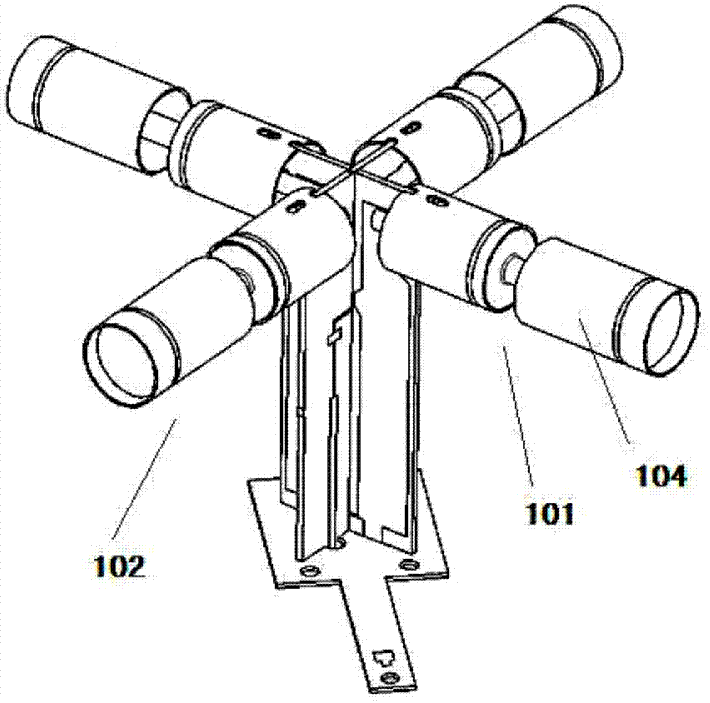
[0035] Such as image 3 As shown, in the low-frequency radiation unit 1, the positive polarized low-frequency vibrator 101 includes two radiating arms symmetrically distributed on the same straight line and a matching circuit connected between the two radiating arms; the negative polarized vibrator 102 also includes symmetrically distributed on the same straight line The two radiating arms and the matching circuit connected between the two radiating arms. The two radiating arms of the positively polarized low-frequency vibrator 101 and the two radiating arms of the negatively polarized low-frequency vibrator 102 are perpendicular to each other and physically disconnected; the matching circuit of the positively polarized low-frequency vibrator 101 and the matching circuit of the negatively polarized low-frequency vibrator 102 are mutually positive Place them crosswise and perpendicular to the metal reflector. The radiation arms of the positively polarized low-frequency vibrator 101 and the negatively polarized low-frequency vibrator 102 are both parallel to the metal reflector.
[0036] As an improvement, the present invention adds at least two choke tubes 104 to each radiation arm of the low-frequency radiation unit 1. The choke tube 104 includes a tubular body and a closed surface arranged on one end surface of the tubular body. The body is fixedly connected with the radiation arm of the low-frequency radiation unit 1 through the closed surface. In the embodiment of the present invention, the end surface of the tubular body where the closed surface is located is the end away from the matching circuit. In other embodiments, the end surface of the tubular body where the closed surface is located may also be the end facing the matching circuit.
[0037] The main function of the choke tube 104 is to suppress the flow of the parasitic current generated by the high-frequency radiation unit 2 on the low-frequency radiation unit 1, so as to reduce the influence of the low-frequency oscillator on the pattern of the high-frequency oscillator.
[0038] As an improvement, two parasitic vibrators 103 are further provided on both sides of the low-frequency radiating unit 1. The two parasitic vibrators 103 are respectively arranged on both sides of the low-frequency vibrator 1, and are fed by coupling the radiation arms of the low-frequency vibrator to Adjust the vertical polarization component of far-field radiation and improve beam convergence.
[0039] Combine figure 2 As shown, in the embodiment of the present invention, two high-frequency radiation units 2 are distributed between every two adjacent low-frequency radiation units 1; that is, in each column of the high-frequency array, there are two adjacent low-frequency radiation units 1 There is one high-frequency radiation unit 2. The distance between the high-frequency radiation units 2 is d, and the distance between the low-frequency radiation units is D, and the relationship between them is: D=2*d. Under such a layout, the orthographic projections of the low-frequency radiation unit 1 and the high-frequency radiation unit 2 on the metal reflector do not overlap each other, which effectively reduces the electrical interference between the two.
[0040] In the embodiment of the present invention, each column of the high-frequency array belongs to an independent high-frequency system. Such as Figure 4 As shown, the high-frequency radiation units 2 on the second reference line and the third reference line belong to different high-frequency systems, respectively. In other words, there are two independent high-frequency systems in the embodiment of the present invention, namely Figure 4 The selected part in the two rectangular boxes. The two high-frequency systems can work in different frequency bands, or in the same frequency band, and jointly cover the 1710-2690MHz frequency band. At the same time, the low-frequency radiating unit 1 on the first reference line covers the 694-960MHz frequency band; therefore, this The embodiment of the invention contains 3 systems, that is, a three-band array antenna in which a low frequency system and two high frequency systems coexist.

Example Embodiment

[0041] Example two
[0042] In a multi-band array antenna, reducing the overlap of the orthographic projection of each frequency band antenna on the metal reflector, or even making them non-overlapping each other, can effectively reduce the electrical interference between the antennas of each frequency band. In the first embodiment, if the orthographic projections of the low-frequency radiation unit 1 and the high-frequency radiation unit 2 on the metal reflector are to be avoided, the length of the two low-frequency vibrators in the low-frequency radiation unit 1 must be limited to avoid the low-frequency vibrator from touching When the high-frequency vibrator is encountered, this limits the radiation characteristics of the low-frequency radiation unit 1 to a certain extent.
[0043] Such as Figure 5 with Image 6 As shown, the embodiment of the present invention is improved on the basis of the first embodiment. Specifically, the end of the low-frequency vibrator also has a bending section, and the bending section is arranged at the end of the low-frequency vibrator in the horizontal direction. Tilt up and down in the vertical direction. In the embodiment of the present invention, the bending section is bent to both sides of the low-frequency radiation unit 1, the extension direction of the bending section is perpendicular to the extension direction of the low-frequency array, and the bending section is located between two adjacent high-frequency radiation units 2 between. This structure extends the length of the low-frequency vibrator, enhances the radiation characteristics of the low-frequency radiation unit 1, and avoids the coincidence of the orthographic projections of the low-frequency radiation unit 1 and the high-frequency radiation unit 2 on the metal reflector (such as Image 6 As shown), the mutual influence between high and low frequencies is reduced, and the isolation of the same frequency array is improved. In other embodiments, the bending section may also be inclined upward or downward at the end of the low-frequency vibrator to adjust the lobe width of the low-frequency radiation unit 1.
[0044] As an improvement, a choke tube 104 may also be provided on the bending section.
[0045] The other technical details of the embodiment of the present invention are the same as the first embodiment, and will not be repeated here.

Example Embodiment

[0046] Example three
[0047] Such as Figure 7 As shown, the embodiment of the present invention is modified on the basis of the second embodiment, and provides an ultra-wideband five-band array antenna. Specifically, the multiple high-frequency radiation units in each column of the high-frequency array in the embodiment of the present invention are divided into two parts from the middle, and are respectively subordinate to two mutually independent high-frequency systems. In other words, the embodiment of the present invention has four independent high-frequency systems, which are Figure 7 The part selected by the four rectangular boxes, plus another low-frequency system, constitutes a five-band array antenna where one low-frequency system and four high-frequency systems coexist.
[0048] Other features in the embodiment of the present invention are the same as those in the second embodiment, so they will not be repeated here.

PUM

no PUM

Description & Claims & Application Information

We can also present the details of the Description, Claims and Application information to help users get a comprehensive understanding of the technical details of the patent, such as background art, summary of invention, brief description of drawings, description of embodiments, and other original content. On the other hand, users can also determine the specific scope of protection of the technology through the list of claims; as well as understand the changes in the life cycle of the technology with the presentation of the patent timeline. Login to view more.

Similar technology patents

Classification and recommendation of technical efficacy words

  • Simple and compact structure
  • Flexible arrangement

Opening-nozzle saddle-shaped seam welding equipment

Owner:BEIJING INSTITUTE OF PETROCHEMICAL TECHNOLOGY

Strip-type Wongawilli mining method of coal buried under building

InactiveCN102587914AFlexible arrangementImprove the recovery rate of coal resourcesUnderground miningSurface miningCoal pillarEngineering
Owner:HENAN POLYTECHNIC UNIV

Device and process for mass production of nanometer fiber by melt electro-spinning method

ActiveCN102839431AMelt thinningFlexible arrangementSpinnerette packsFilament/thread formingMelt blowingNanofiber
Owner:BEIJING UNIV OF CHEM TECH

Method for establishing task management system software virtual test environment

InactiveCN107992411AMeet the requirements for completing configuration item testingFlexible arrangementSoftware testing/debuggingEmbedded operating systemVirtual test
Owner:XIAN AIRCRAFT DESIGN INST OF AVIATION IND OF CHINA
Why Eureka
Try Eureka