Multi-roll oil removal machine with built-in blowing and suction devices and strip oil removal method

A technology of suction device and degreasing machine, used in metal processing equipment, metal rolling, manufacturing tools, etc., can solve the problems of increasing the difficulty of strip annealing treatment, high noise of compressed air purging, slippage or dislocation, etc.

Active Publication Date: 2015-01-14
北京斯蒂尔罗林科技发展有限公司
View PDF6 Cites 4 Cited by
  • Summary
  • Abstract
  • Description
  • Claims
  • Application Information

AI Technical Summary

Problems solved by technology

[0002] During the processing of metal materials, due to the needs of the rolling process, a large amount of process lubricants, such as rolling oil, water, emulsion, etc., should be sprayed on the metal surface. After rolling, a part of the process lubricants will adhere to the surface of the metal strip. If it is involved in the coiler, it is easy to cause slippage or misalignment, which will affect production, increase the difficulty of annealing the strip, and affect the surface quality of the finished strip. At the same time, it will increase the consumption of process lubricating fluid. Finally, set up cleaning equipment to remove the residual process lubricant on the metal surface
At present, the commonly used degreasing devices include roller degreasing, vacuum roller degreasing, belt degreasing, air blowing, cloth clip degreasing, etc. These degreasing devices are respectively suitable for different cold-rolled strips Degreasing, each has its own characteristics, but there are still roller degreasing and vacuum roller degreasing effects that are not good, traditional compressed air blowing noise is loud and pollutes the surrounding environment and affects the health of operators. Cloth clamp degreasing can only be used in Disadvantages such as use at low speed

Method used


Image

  • Multi-roll oil removal machine with built-in blowing and suction devices and strip oil removal method
  • Multi-roll oil removal machine with built-in blowing and suction devices and strip oil removal method
  • Multi-roll oil removal machine with built-in blowing and suction devices and strip oil removal method

Examples


Embodiment 1

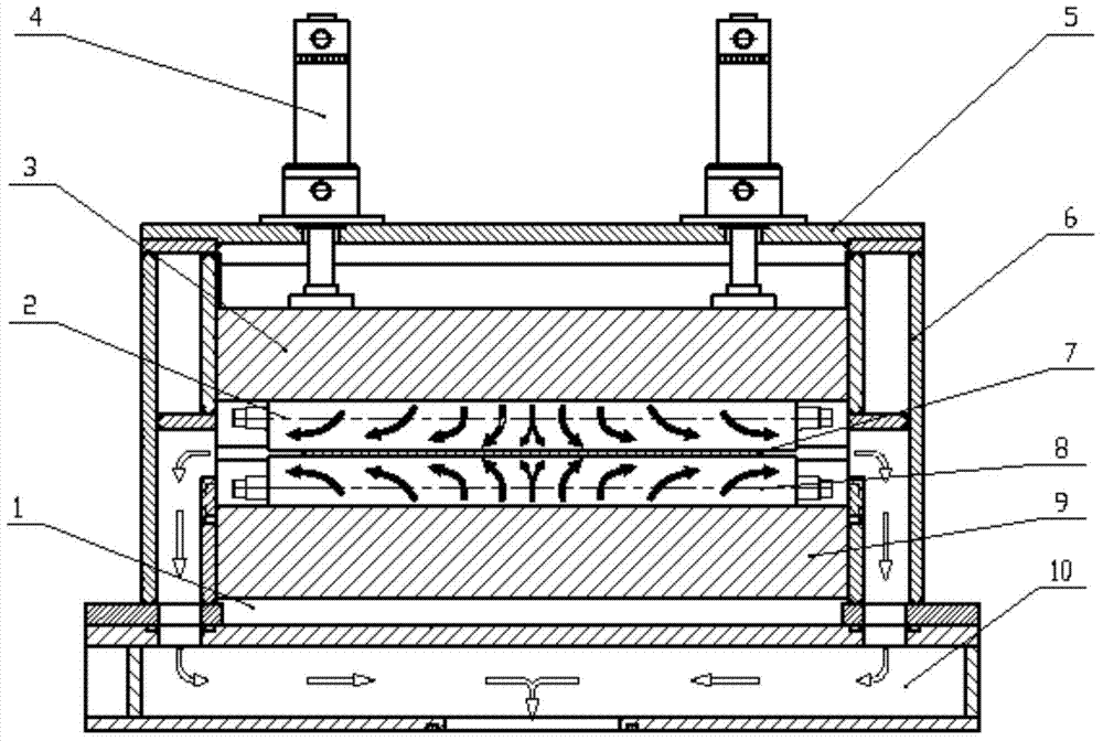
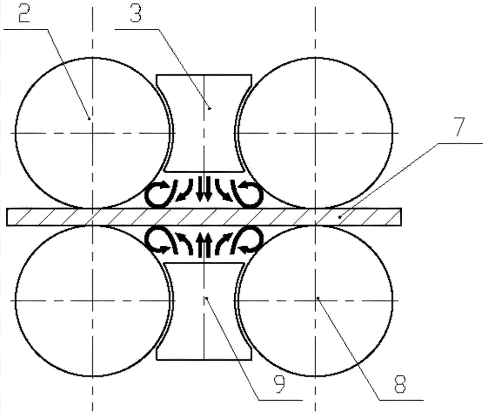
[0026] Such as figure 1 , 2 As shown, a multi-roll degreaser with built-in purging and suction devices includes a frame, multiple degreasing rollers, a purging device, a suction device and a sewage collection system. A plurality of degreasing rollers are all installed in the frame 1, and a plurality of degreasing rollers are arranged up and down the strip material 7, and are divided into an upper degreasing roller 2 and a lower degreasing roller 8 with the strip material 7 as a boundary.

[0027] There is a purging device between the upper degreasing rollers and between the lower degreasing rollers. The purging device is in close contact with the two adjacent degreasing rollers. The upper degreasing roller and the lower degreasing roller correspond to the strip. The lower two pairs of degreasing rollers are in contact with the strip to form a closed chamber composed of the strip, degreasing rollers, purging device and frame. The suction device communicates with the closed ca...

Embodiment 2

[0042] The height of the degreasing roller is changed by the lifting device so that the upper and lower degreasing rollers clamp the strip to form a closed cavity surrounded by the strip, the degreasing roller, the purging device between the degreasing rollers and the frame. Use the purging device to purge the residual process lubricating liquid on the surface of the strip with compressed air at high pressure and low flow to form mist, and then suck it away through the suction device with low pressure and high flow. The strip moves between the upper and lower degreasing rollers, and the remaining process lubricating fluid on the strip is purged and degreased section by section, and then the degreasing of the entire strip is completed.

[0043] In this embodiment, a strip degreasing method is implemented on a multi-roll degreasing machine with built-in purge and suction devices as described in Embodiment 1, and the upper and lower parts are moved by a plurality of lifting device...


PUM


Abstract

The invention provides a multi-roll oil removal machine with built-in blowing and suction devices. The multi-roll oil removal machine comprises a rack, a plurality of oil removal rolls, blowing devices and a suction device, wherein the oil removal rolls are arranged in the rack and are arranged above and below a strip respectively; the blowing devices are arranged between upper oil removal rolls as well as between lower oil removal rolls; the upper and lower oil removal rolls are contacted with the strip to form a closed cavity which is defined by the strip, the oil removal rolls, the blowing devices and the rack; the blowing devices are communicated with the closed cavity; the suction device is communicated with the closed cavity through a passage. The noise and the pollution can be reduced and the technological lubricating oil can be saved during work. The invention also provides a strip oil removal method. The closed cavity is formed by making the upper and lower oil removal rolls in contact with the strip ; the blowing devices are arranged in the closed cavity to blow liquid remained on the surface of the strip through high-pressure low-flow compressed air to form fog; the suction device is used for sucking the fog from the two ends of the closed cavity in the axial direction of the oil removal rolls in a low-pressure high-flow mode to achieve an oil removal purpose.

Description

technical field [0001] The invention relates to a degreasing machine and a degreasing method, in particular to a multi-roll degreasing machine with built-in purge and suction devices and a strip degreasing method, belonging to the field of metal material processing machinery and methods. Background technique [0002] During the processing of metal materials, due to the needs of the rolling process, a large amount of process lubricants, such as rolling oil, water, emulsion, etc., should be sprayed on the metal surface. After rolling, some process lubricants will adhere to the surface of the metal strip. If it is involved in the coiler, it is easy to cause slippage or misalignment, which will affect production, increase the difficulty of annealing the strip, affect the surface quality of the finished strip, and increase the consumption of process lubricating fluid. Finally, set up cleaning equipment to remove residual process lubricants on the metal surface. At present, the c...

Claims


Application Information

Patent Timeline
Patent Type & Authority Applications(China)
IPC IPC(8): B21B45/02
Inventor 王宇
Owner 北京斯蒂尔罗林科技发展有限公司
Why Eureka
Try Eureka