
Cutting machine

A cutting machine and casing technology, applied in the direction of shearing devices, metal processing machinery parts, maintenance and safety accessories, etc., can solve the problems of personal injury, loss, etc., to ensure safety, avoid work stagnation, and good impact resistance Effect

Inactive Publication Date: 2015-01-14
中山市鸿程科研技术服务有限公司
View PDF6 Cites 1 Cited by
  • Summary
  • Abstract
  • Description
  • Claims
  • Application Information

AI Technical Summary

Problems solved by technology

[0002] Iron-chromium-aluminum alloy contains a large amount of chromium and aluminum elements, so the alloy has excellent oxidation resistance and high resistivity, and the price of iron-chromium-aluminum alloy is cheap, only 20%-25% of nickel-chromium alloy, which is Extensive use has created conditions, and at the same time led to the rapid development of metal alloys, especially the cutting machine as one of the indispensable machinery in its processing and manufacturing process. A cutting machine generally includes a shell and a When using a disc knife and a motor, the disc knife rotates quickly to achieve the purpose of cutting iron-chromium-aluminum alloys. However, since the disc knife blade is exposed outside when cutting materials, if you do not pay attention to the relationship between the hand and the blade during the production process distance, it is easy to cause great harm to the person, such as a cutting machine whose Chinese patent number is CN202780022U. Yes: The debris generated by cutting profiles can be thrown into the debris collection bag by the centrifugal force generated when the saw blade is cut, avoiding the heat brought by the flying debris and the impact of sparks on the surrounding environment. It is easy to use and easy to carry. It improves the safety of the cutting machine, but this solution does not solve the disadvantages that the exposed blade in the cutting production process will cause great harm to the person and cause huge losses if you do not pay attention

Method used

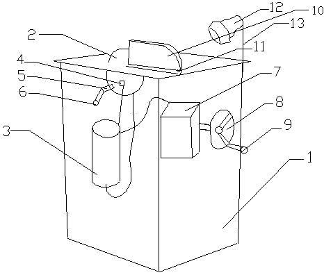

Image

  • Cutting machine
  • Cutting machine

Examples


Embodiment Construction

[0013] In order to make the technical means, creative features, goals and effects achieved by the present invention easy to understand, the present invention will be further described below in conjunction with specific embodiments.

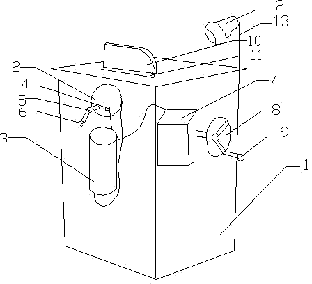
[0014] like figure 1 and figure 2 As shown, a cutting machine includes a housing 1, a disc cutter 2, and a motor 3. The housing 1 is connected to the disc cutter 2, the disc cutter 2 is connected to the motor 3, and the housing 1 is connected to the motor 3. The motor 3 is connected, the disc cutter 2 is provided with a bimetal temperature control device 4, the bimetal temperature control device 4 is connected in series with the motor 3, a protective shell 10 is arranged above the disc cutter 2, and the The casing 1 is provided with a chute 11, the protective shell 10 is connected to the chute 11, the disc cutter 2 is a tungsten-cobalt hard alloy saw blade, and the thickness of the disc cutter 2 is 4.0-4.8mm. The cutting machine is 70-90cm hig...


PUM

PropertyMeasurementUnit
Thicknessaaaaaaaaaa

Abstract

The invention relates to the field of metal alloy, in particular to a cutting machine, comprising a shell, a cutting disc and a motor; the shell is connected with the cutting disc connected with the motor; the shell is connected with the motor; a dual metal sheet temperature control device is arranged in the cutting disc and is connected with the motor in series; a protection shell is arranged above the cutting disc; a chute is formed in the shell and is connected with the protection shell; the cutting disc is a tungsten cobalt hard alloy saw blade; the cutting machine is 70-90cm high. The normal functions of the cutting machine are not influenced while the possible harm to a human body caused by the cutting disc under an inattention condition can be avoided, and the operation safety and cleanliness are ensured; the cutting disc uses the tungsten cobalt hard alloy saw blade having good impact resistance, harness and rigidity, and the machining period is greatly shortened while a flat cutting surface of a cut object is ensured.

Description

technical field [0001] The invention relates to the field of metal alloys, in particular to a cutting machine. Background technique [0002] Iron-chromium-aluminum alloy contains a large amount of chromium and aluminum elements, so the alloy has excellent oxidation resistance and high resistivity, and the price of iron-chromium-aluminum alloy is cheap, only 20%-25% of nickel-chromium alloy, which is Extensive use has created conditions, and at the same time led to the rapid development of metal alloys, especially the cutting machine as one of the indispensable machinery in its processing and manufacturing process. A cutting machine generally includes a shell and a When using a disc knife and a motor, the disc knife rotates quickly to achieve the purpose of cutting iron-chromium-aluminum alloys. However, since the disc knife blade is exposed outside when cutting materials, if you do not pay attention to the relationship between the hand and the blade during the production pro...

Claims


Application Information

Patent Timeline
IPC IPC(8): B23D19/00B23D33/00B23D35/00B23Q11/06
Inventor 李丽娟王建武
Owner 中山市鸿程科研技术服务有限公司
Learn More