
Equipment and method for removing and recovering sludge at the bottom of a crude oil storage tank

A technology for crude oil storage tanks and recovery equipment, which is applied in the field of cleaning and recovery of sludge at the bottom of crude oil storage tanks. It can solve the problems of inability to use the main cleaning cycle system in series, high operating costs, and poor economy, and achieves reductions in cleaning treatment costs and equipment. The effect of low investment and improved operational flexibility

Active Publication Date: 2016-05-25
北京蓝星清洗有限公司
View PDF5 Cites 1 Cited by
  • Summary
  • Abstract
  • Description
  • Claims
  • Application Information

AI Technical Summary

Problems solved by technology

Since the processing capacity of the three centrifuges is generally less than 15m 3 / h, when the solid content is large, the processing capacity is even less than 5m 3 / h, cannot be used in series with the main cleaning cycle system, it can only be used as a parallel bypass processing system
Because the processing capacity of the three-phase centrifuge is too small, when the amount of sludge is large or the content of inorganic solid matter is large, two or more three-phase centrifuge systems need to be used at the same time. This method requires too much investment and high operating costs. , less economical

Method used


Image

  • Equipment and method for removing and recovering sludge at the bottom of a crude oil storage tank
  • Equipment and method for removing and recovering sludge at the bottom of a crude oil storage tank
  • Equipment and method for removing and recovering sludge at the bottom of a crude oil storage tank

Examples


Embodiment 1

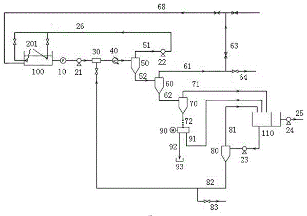
[0053] Such as figure 1 As shown, the suction pump 21 extracts the "oil-water-sand" mixture from the cleaned crude oil storage tank 100, and the "oil-water-sand" passes through the filter 10 before the pump and flows into the mixer 30; The water storage side in the type oil-water separator 110 is drawn out, and through the deoiling hydrocyclone 80, the deoiling hydrocyclone 80 further separates the water containing a small amount of oil from the gravity type oil-water separator 110, and the rich The oily water flows back to the oil-water separator 110 from the overflow port, and the oil-poor water flows out from the bottom flow port, and is input into the mixer 30 through the pipeline 82, and the used mixer is a static mixer. Here, water is thoroughly mixed with the "oil-water-sand" mixture from the crude oil storage tank 100, and the amount of water added should be sufficient to make the volume content of water in the material in the mixer 30 greater than 50%, and to ensure t...

Embodiment 2

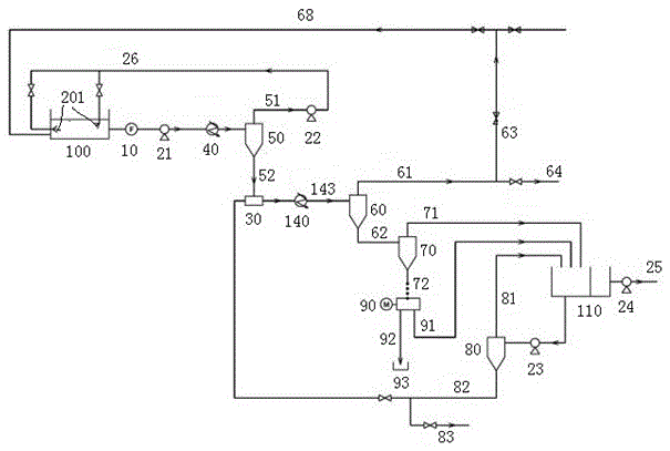
[0060] Such as figure 2 As shown, the suction pump 21 extracts the "oil-water-sand" mixture from the cleaned crude oil storage tank 100, passes through the pre-pump filter 10, flows into the heater 40, and heats up to a suitable temperature for cleaning and hydrocyclone separation.

[0061] The heated material enters the screening hydrocyclone 50, where the "oil-water-sand" mixture is initially separated into two parts with a smaller specific gravity and a larger specific gravity. The split ratio of the screening hydrocyclone 50 is controlled so that the overflow The flow rate out of the outlet matches the flow rate of the cleaning pump 22, and the lighter material with more oil and less water and sand flowing out from the overflow port passes through the first pipeline 51, the cleaning cleaning pump 22, and then is sprayed at high pressure by the cleaning nozzle 201 to On the sludge at the bottom of the crude oil storage tank 100, the sludge is cut, stirred, and under the co...


PUM

PropertyMeasurementUnit
diameteraaaaaaaaaa

Abstract

The invention relates to equipment for clearing away and recovering sludge at the bottom of a crude oil storage tank. The equipment comprises the crude oil storage tank (100) and is characterized by comprising a suction pump (21), wherein an input end of the suction pump (21) is connected with the crude oil storage tank (100), a heater (40), a screened suspension separator (50), a main separated suspension separator (60), a sand removal separator (70), a sludge dehydrator (90), a gravity type oil-water separator (110) and an oil removal suspension separator (80) are sequentially arranged at an output end of the suction pump (21), a mixer (3) is arranged between the heater (40) and the screened suspension separator (50) or between the screened suspension separator (50) and the main separated suspension separator (60), and the mixer (30) is connected with an underflow opening of the oil removal suspension separator (80) through a pipeline. An overflow opening of the screened suspension separator (50) is sequentially connected with a cleaning pump (22) and a cleaning nozzle (201). A filter (10) is arranged between the suction pump (21) and the crude oil storage tank (100).

Description

technical field [0001] The invention belongs to the technical field of cleaning and recovery of sludge at the bottom of crude oil storage tanks, and in particular relates to equipment and a method for cleaning and recovery of sludge at the bottom of crude oil storage tanks. Background technique [0002] Crude oil is a complex mixture, which is often stored in external floating roof storage tanks with a diameter of 60-80M. When crude oil is stored in the storage tank, due to the decrease of flow rate and storage temperature, mechanical impurities, corrosion products, sand, soil, heavy metal salts, paraffin, asphaltenes, colloids, etc. Due to the difference in specific gravity, the heavy components gradually settle and accumulate at the bottom of the storage tank naturally, forming a black sticky jelly, which is called "sludge" at the bottom of the crude oil tank. These tank bottom sludges are a stable, multiphase mixture of oil, water, and solids in a semi-solid form. The t...

Claims


Application Information

Patent Timeline
Patent Type & Authority Patents(China)
IPC IPC(8): C02F11/00C02F9/10C02F11/12
CPCC02F11/00C02F11/121C02F11/128C02F2303/06
Inventor 康波娄笼筑张季愚李岑
Owner 北京蓝星清洗有限公司
Learn More