
A led plant lighting system

A lighting system and LED light source technology, which is applied in the field of LED lighting, can solve the problems of inhibiting plant photosynthesis, and achieve the effects of avoiding internal and external time asymmetry, enhancing disease resistance, and promoting growth

Active Publication Date: 2016-12-07
深圳莱特光电股份有限公司
View PDF6 Cites 0 Cited by
  • Summary
  • Abstract
  • Description
  • Claims
  • Application Information

AI Technical Summary

Problems solved by technology

On the other hand, the traditional LED plant lighting system only simply imitates the intensity of light in the natural environment, while ignoring the environmental temperature, relative humidity and suspended particles that will affect the light and even the physiological conditions of plants. For example, when the relative humidity is high, suspended particles Water mist will block light waves with shorter wavelengths (such as blue light, green light, ultraviolet light, etc.), and the light energy that plants can convert into photosynthesis is precisely light with shorter wavelengths, so too high relative humidity will inhibit photosynthesis of plants

Method used


Image

  • A led plant lighting system
  • A led plant lighting system
  • A led plant lighting system

Examples


Embodiment 1

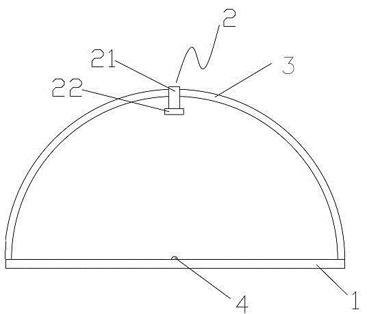
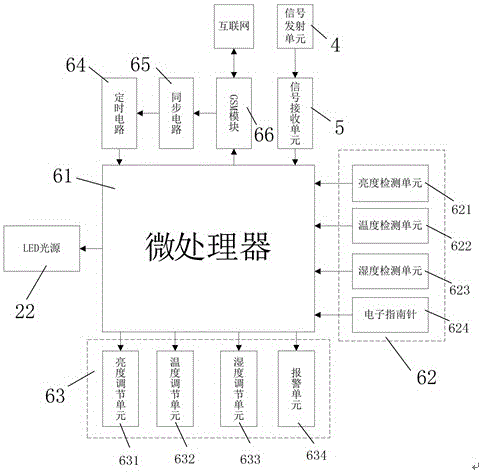
[0048] This example figure 1 As shown, an LED plant lighting system includes a base 1, a lamp body 2 and an outer frame 3 connected to the lamp body 2, the outer frame 3 is bow-shaped, and the lamp body 2 is suspended from the outer frame 3 Above, the main body of the lamp 2 can move along the outer frame 3; The signal transmitting unit 4 is provided with a signal receiving unit 5 in the control circuit. The signal transmitting unit 4 is wirelessly connected with the signal receiving unit 5 .

[0049] As a preferred option, such as Figure 8 As shown, the lamp board 7 of the LED light source 22 in this embodiment is provided with red LED chips, blue LED chips and ultraviolet LED chips, and three kinds of light-emitting diodes 8 are arranged in a staggered manner on the lamp board 7 .

[0050] As a preferred option, such as Figure 6 and Figure 7 As shown, in this embodiment, the inner side of the outer frame 3 is provided with a slide rail 31 matching its shape, and the ...

Embodiment 2

[0097] Using the system of Example 1, tobacco seedlings were grown.

[0098] Specifically include the following steps:

[0099] Including the following procedures:

[0100] a. Select tobacco seeds with full particles and plant them in the seedbed. After spraying 100mL germination solution per 1kg of seeds, they are irradiated with infrared light with a wavelength of 800nm ​​for 5min every 6 hours, irradiated with ultraviolet light with a wavelength of 260nm for 30s, and then irradiated with 650nm After irradiating with red light for 30 minutes, place it in shading;

[0101] b. After the seeds germinate, cultivate them in shading until the length of the seedlings is 4-6cm;

[0102] c. Spray 50mL of rooting solution for every 5 seedlings, and irradiate them with 455nm blue light for 2 hours and 830nm infrared light for 3 hours every 12 hours until the seedlings grow more than 5 true leaves;

[0103] d. Transplant the seedlings into a solid substrate, every 20cm 2 Transplant ...


PUM


Abstract

The invention relates to an LED plant illumination system which comprises a base (1), a lamp body (2) and an outer frame (3) connected with the lamp body. The LED plant illumination system is characterized in that the outer frame is arch, the lamp body is suspended on the outer frame, and the lamp body can move along the outer frame. The lamp body is composed of a suspension rod (21) and an LED light source (22) arranged at the lower end of the suspension rod. Compared with the prior art, the LED plant illumination system has the following advantages: the growing environment of plants is highly simulated, and plants also can grow normally even in the indoor environment; the growing environment of the plants can be controlled intelligently, and the plants can be located in the environment most suitable for growth according to the requirement of a user whether in winter or in summer; the LED plant illumination system can be connected to the internet, time synchronization is conducted, and the internal and external time dissymmetry caused by power failures and the like is effectively avoided.

Description

technical field [0001] The invention relates to the field of LED lighting, in particular to an LED plant lighting system. Background technique [0002] With the continuous improvement of living standards and the advancement of technology, people's demand for fresh vegetable plants is also increasing. Using greenhouse planting technology can shorten the production cycle of plants and produce off-season seasonal vegetables to meet people's needs. Appropriate light and temperature are necessary conditions for plant production. Vegetables grown in greenhouses often have insufficient light, especially in the cold winter season, and it is difficult to reach a suitable temperature for plant production. Therefore, artificial supplementary light and heating auxiliary measures can be used , to create suitable growth conditions for plants. [0003] my country has gradually applied LED lights to the field of modern agricultural production in the first ten years of the 21st century. Be...

Claims


Application Information

Patent Timeline
Patent Type & Authority Patents(China)
IPC IPC(8): F21S8/00F21V23/00H05B37/02A01G9/20
CPCA01G7/045F21S8/06F21V19/001F21V23/003F21V23/045F21Y2101/00H05B47/11Y02B20/40Y02P60/14
Inventor 冯海涛施光典
Owner 深圳莱特光电股份有限公司
Learn More