A sample axial erosion corrosion test device and method

A technology of erosion corrosion and test equipment, which is applied in the direction of measuring equipment, weather resistance/light resistance/corrosion resistance, instruments, etc., can solve the problems of high performance requirements of mechanical pumps, high construction and operation costs, low fluid flow rate, etc., to achieve the test Effects of compact device, large device scale, and low construction and operation costs

Inactive Publication Date: 2016-09-07
HEFEI INSTITUTES OF PHYSICAL SCIENCE - CHINESE ACAD OF SCI
View PDF5 Cites 0 Cited by
  • Summary
  • Abstract
  • Description
  • Claims
  • Application Information

AI Technical Summary

Problems solved by technology

[0002] In the existing high-temperature fluid devices, there are mainly two driving methods for the fluid: heat convection and mechanical pump drive. The disadvantages are: the flow rate of the fluid driven by heat convection is generally small, and it is not suitable for fluids with high viscosity; The driven fluid generally has a large flow rate. The disadvantage is that some special high-temperature and highly corrosive fluids have high requirements on the performance of the mechanical pump, and the test device driven by the mechanical pump is generally large-scale, and the construction and operation costs are high.

Method used


Image

  • A sample axial erosion corrosion test device and method
  • A sample axial erosion corrosion test device and method
  • A sample axial erosion corrosion test device and method

Examples


Embodiment 1

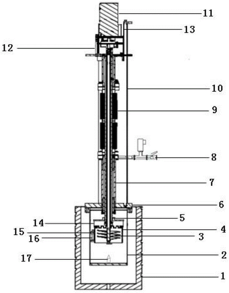
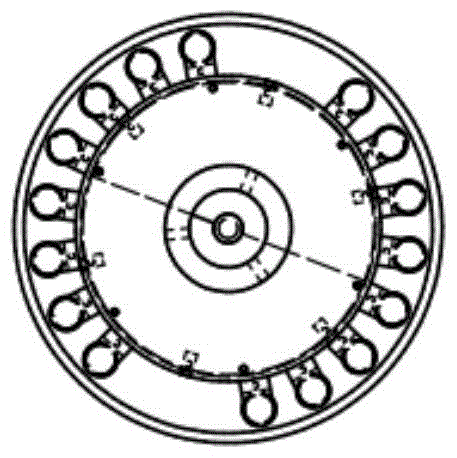
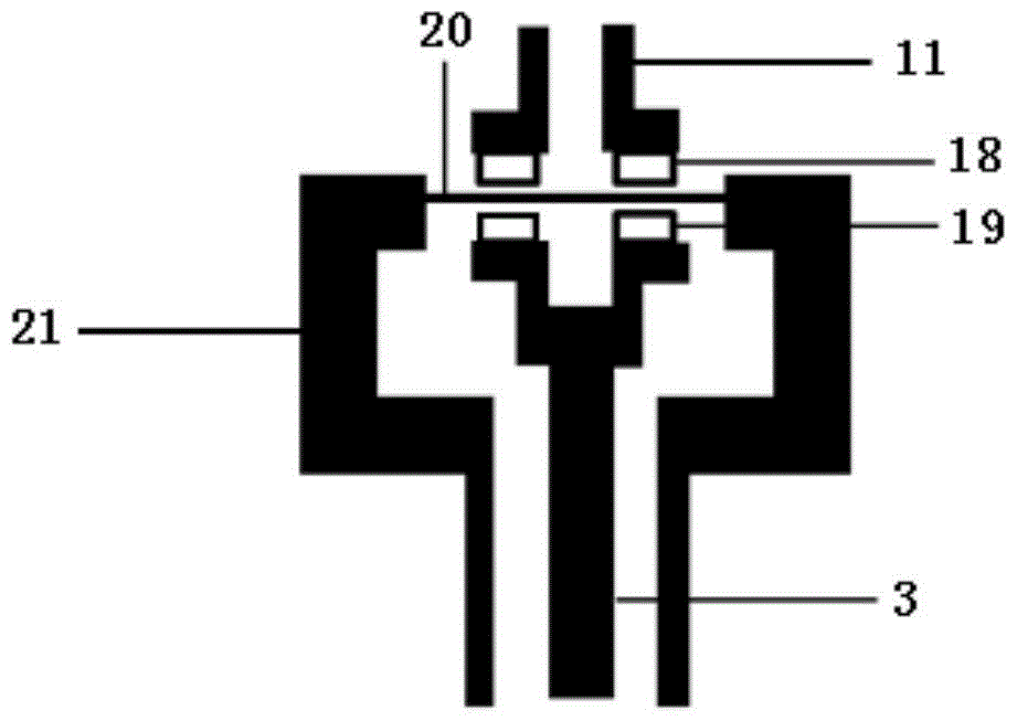
[0043] Implementation Example 1: According to the above description, a liquid lead-bismuth alloy corrosion experiment device was designed and developed and a corrosion experiment was carried out. The motor 11 is a high-power stepping motor; the number of threads of the screw type stirring paddle 3 is 3.5; the sample 16 is 16 outer Stainless steel hollow rods with the same diameter and height, the sample 16 is installed and fixed on the outer wall of the guide tube 4 through the sample holder 15. The corrosion test procedure is as follows:

[0044] (1) Add a solid lead-bismuth block with a calculated weight into the tank body 2, put the guide tube 4 and the screw-type stirring paddle 3 with the sample 16 installed, and seal the tank body top cover 6.

[0045] (2) Open the vacuum system 8, replace the air in the bellows 9 and the tank body 2 with argon, and close the vacuum system 8.

[0046] (3) Open the heating and heat preservation system 1 outside the tank body 2 to heat th...

Embodiment 2

[0052] Implementation example 2: Use water to calibrate the driving efficiency of the corrosion experimental device, the calculation process is as follows:

[0053] η = 4 × Q π × ( D 2 - d 2 ) × ( H - h ) × ω

[0054] In the formula:

[0055] η is the driving efficiency of the test device;

[0056] D is the diameter of the screw type impeller;

[0057] d is the diameter of the drive shaft of the screw-type stirring paddle;

[0058] H is the pitch of the screw-type stirring paddle blade;

[0059] h is t...


PUM


Abstract

The invention relates to an axial erosion corrosion test device and method for samples. The axial erosion corrosion test device comprises a heating thermal insulation system, a tank body, a screw-type stirring paddle, a flow guide cylinder, a connecting bar, a coupling flange, a tank body top cap, a direction guide cylinder, a vacuum system, a corrugated pipe, a positioning rod, a motor, a magnetic connecting shaft transmission piece, a lifting system, a sample clamp, a sample, an ejector and other structural parts. The working principle of the axial erosion corrosion test device is that the motor drives an outer magnet to rotate, rotary motion is conveyed to an inner magnet under the action of the magnetic force, the inner magnet rotates to drive the screw-type stirring paddle to rotate, fluid in the tank body is driven to flow circularly in the vertical direction, and the sample clamp used for fixing the sample is mounted on the outer wall of the flow guide cylinder, so that the fluid erodes the sample in the axial direction. The axial erosion corrosion test device has the positive result that only a simple tank stirring structure is adopted to achieve axial erosion of the sample.

Description

technical field [0001] The invention relates to a sample axial erosion corrosion test device and method, which are used to realize the surface erosion test of pipe and bar samples. Background technique [0002] In the existing high-temperature fluid devices, there are mainly two driving methods for the fluid: heat convection and mechanical pump drive. The disadvantages are: the flow rate of the fluid driven by heat convection is generally small, and it is not suitable for fluids with high viscosity; The driven fluid generally has a large flow rate. The disadvantage is that some special high-temperature and highly corrosive fluids have high requirements on the performance of the mechanical pump, and the test device driven by the mechanical pump is generally large in scale, and the construction and operation costs are high. [0003] For some special fluids, such as liquid lead-bismuth alloy, the temperature is high, the chemical properties are active, and the corrosion is stro...

Claims


Application Information

Patent Timeline
Patent Type & Authority Patents(China)
IPC IPC(8): G01N17/00
Inventor 梅华平韩骞陈建伟吴庆生黄群英
Owner HEFEI INSTITUTES OF PHYSICAL SCIENCE - CHINESE ACAD OF SCI
Why Eureka
Try Eureka