
Novel fiber optic gyro interference light path based on photonic crystal fiber

A photonic crystal fiber, fiber optic gyroscope technology, applied in Sagnac effect gyroscopes, gyroscopes/steering induction equipment, measurement devices, etc. Unsatisfactory performance and other problems, to achieve the effect of good temperature stability and low magnetic field sensitivity

Active Publication Date: 2015-01-28
BEIJING AEROSPACE TIMES OPTICAL ELECTRONICS TECH
View PDF4 Cites 17 Cited by
  • Summary
  • Abstract
  • Description
  • Claims
  • Application Information

AI Technical Summary

Problems solved by technology

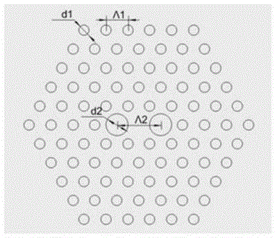
The process of photonic bandgap optical fiber is quite complicated. So far, the loss of optical fiber is relatively large, and the performance of polarization maintenance is not ideal. However, the refractive index guided solid core photonic crystal fiber is relatively mature and has the potential to be used in fiber optic gyroscopes. Base

Method used


Image

  • Novel fiber optic gyro interference light path based on photonic crystal fiber
  • Novel fiber optic gyro interference light path based on photonic crystal fiber
  • Novel fiber optic gyro interference light path based on photonic crystal fiber

Examples


Embodiment Construction

[0021] Compared with the traditional interferometric fiber optic gyroscope, the biggest difference of the photonic crystal fiber optic gyroscope is that the photonic crystal fiber is used to wind the fiber ring. Based on the difference of the fiber type, it can be divided into the refractive index guided type and the bandgap type. The present invention adopts the refraction Guided photonic crystal fiber. Taking a fiber optic gyroscope using a 500-meter photonic crystal fiber as an example, the specific implementation is described.

[0022] (1) Photonic crystal fiber end face structure design

[0023] Using the finite element numerical calculation method to solve the fundamental mode of the photonic crystal fiber, the birefringence B and the mode field area A of the optical fiber are obtained through the mode field distribution and the equivalent refractive index of the fundamental mode eff and the limiting loss L, which can be expressed as:

[0024] B ...


PUM


Abstract

A novel fiber optic gyro interference light path based on photonic crystal fiber includes a photonic crystal fiber ring and a Y waveguide integrated optical device. The optical fiber ring adopts an refractive index guided photonic crystal fiber; for winding of the fiber ring, a mode of solidifying one layer after winding is employed; and the Y waveguide tail fiber employs the same type of fiber as the optical fiber ring. The design of photonic crystal fiber meets the requirements of birefringence of gyro and at the same time has the mode field as Y waveguide chip, and a shrinkage cavity method is used for further expansion of the field mode of the optical fiber, so as to reduce additional loss caused by optical fiber splicing. The designed interference optical path has the characteristics of good polarization stability, low magnetic field polarization sensitivity and radiation resistance; the fiber optic gyro using the interference light path has the characteristics of radiation resistance, good temperature stability and low magnetic field sensitivity, and is especially can be used as high precision fiber optic gyroscope for satellite and other space vehicles.

Description

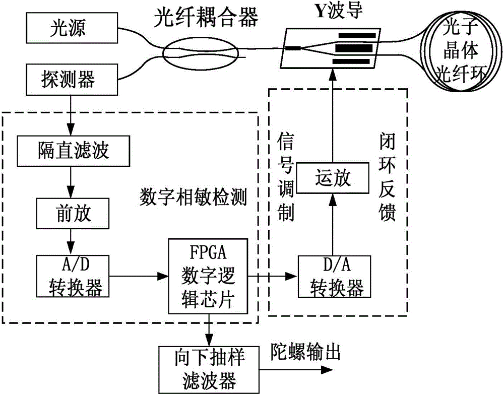
technical field [0001] The invention relates to a novel optical fiber gyroscope interference optical path based on photonic crystal fiber, and belongs to the technical field of optical fiber gyroscopes. Background technique [0002] Due to its small size, light weight, low power consumption, and high reliability, the fiber optic gyroscope has become one of the mainstream instruments in the field of inertial systems and has been widely used in various fields of sea, land, air and space. The block diagram of the fiber optic gyroscope is as follows: figure 1 As shown, the optical path part includes light source, fiber coupler, Y-waveguide integrated optical device, fiber ring and photodetector, wherein the fiber ring is the sensitive part of the fiber optic gyroscope, and the fiber optic gyroscope detects the gap between two beams of light transmitted oppositely in the fiber ring. The phase difference is used to detect the angular velocity to which the gyroscope is sensitive. ...

Claims


Application Information

Patent Timeline
IPC IPC(8): G01C19/72
CPCG01C19/721
Inventor 张志鑫秦伟亮李晶杨学礼张智华黄韬汪飞琴
Owner BEIJING AEROSPACE TIMES OPTICAL ELECTRONICS TECH
Learn More