Cathode cooling structure of plasma spraying gun

A cooling structure, plasma technology, applied in the direction of plasma, electrical components, etc., can solve the problem that the cathode is easy to be ablated, and achieve the effect of simple production, excellent thermal conductivity, and saving production costs

Inactive Publication Date: 2015-01-28
周开根
View PDF8 Cites 7 Cited by
  • Summary
  • Abstract
  • Description
  • Claims
  • Application Information

AI Technical Summary

Problems solved by technology

[0005] The purpose of the present invention is to overcome the shortcoming that the cathode of the existing plasma torch is easily ablated, and to provide a cathode cooling structure of the plasma torch, so that the cathode is not easy to be ablated, so as to prolong the service life of the plasma torch and improve production efficiency. Efficiency and saving production cost

Method used


Image

  • Cathode cooling structure of plasma spraying gun
  • Cathode cooling structure of plasma spraying gun

Examples


Embodiment 1

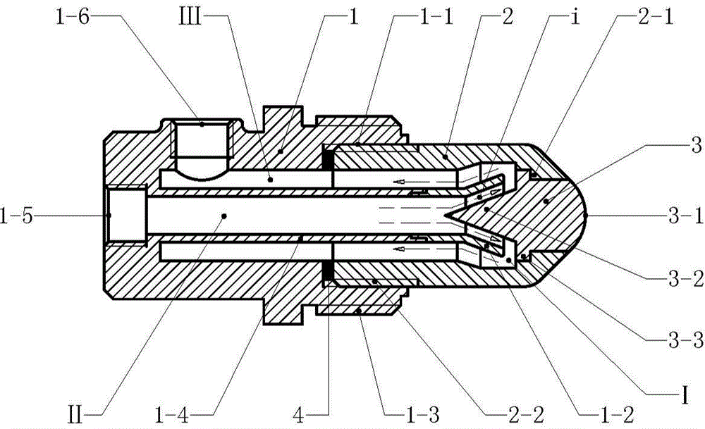
[0014] Example 1 figure 1In the embodiment shown, the cathode cooling structure of the plasma torch is composed of a back seat (1), a cathode sleeve (2) and a cathode head (3), wherein the back seat (1) is a hollow rotary structure, and the back seat ( 1) There are diversion pipes (1-4) in the rotator structure of the rear seat (1), and there are cooling water input ports (1-5) and cooling water output ports (1-6) on the rotator structure of the rear seat (1). There are threaded notches (1-1) on the inner side of the front wall of the back seat (1) rotator, and connecting threads (1-3) on the outer side of the back seat (1) rotator; the cathode sleeve (2) is a hollow rotator structure, there is a mounting screw (2-2) on the outside of the wall at the rear of the cathode sleeve (2), and the mounting screw (2-2) cooperates with the threaded notch (1-1) on the rear seat (1), The front end of the cathode sleeve (2) is a truncated conical structure that shrinks from the back to ...

Embodiment 2

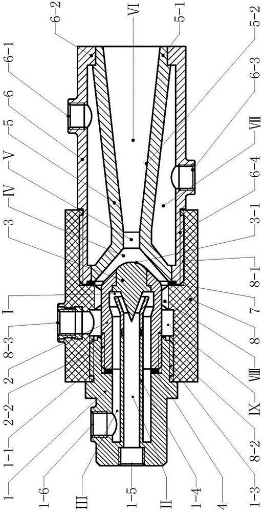
[0015] Example 2 figure 2 The embodiment shown is the application of the present invention on the plasma spray gun, and the plasma spray gun is mainly composed of a back seat (1), a cathode cover (2), a cathode head (3), an insulating gun frame (8), an anode cover (6 ) and the anode (5), wherein the rear seat (1), the cathode sleeve (2) and the cathode head (3) constitute the cathode cooling structure, which is the same as the structure in the first implementation and will not be described in detail; the insulating gun frame (8 ) is a hollow revolving body structure, the front and rear mounting grooves (8-1) and rear mounting grooves (8-2) of the insulating gun frame (8) are respectively provided, and the rotating body structure of the insulating gun frame (8) has an air chamber (Ⅸ), the air chamber (Ⅸ) is connected to the working gas input interface (8-3); the anode sleeve (6) is a cylindrical structure, and the outside of the rear wall of the anode sleeve (6) has mounting...


PUM


Abstract

The invention relates to a cathode cooling structure of a plasma spraying gun. The cathode cooling structure is composed of a rear seat, a cathode sleeve and a cathode head, wherein a guide tube is arranged in a rotation body structure of the rear seat, the cathode sleeve is of a hollow rotation body structure, the internal space of the cathode sleeve forms a cooling cavity, the cathode head is embedded into the front end of the cathode sleeve, the front end of the cathode head extends out of the cathode sleeve, the rear end of the cathode head is a conical cooling tail protrusion, the cooling tail protrusion extends into the cooling cavity, the guide tube on the rear seat extends into the cooling cavity of the cathode sleeve, and a water outlet of the guide tube surrounds the cooling tail protrusion at the rear end of the cathode head. The space between the outer wall of the guide tube and a rear seat wall body serves as a water return channel, the internal space of the guide tube serves as a guiding channel, a cooling water input interface is communicated with the guiding channel, the guiding channel is communicated with the water return channel through the surrounding space of the cooling tail protrusion at the rear end of the cathode head. The cathode cooling structure cools the cathode head in a close flushing mode and can quickly carry away heat of the cathode head and enable a cathode not to be easily ablated.

Description

technical field [0001] The invention relates to plasma equipment, in particular to a cathode structure of a plasma torch. Background technique [0002] At present, plasma technology has been widely used, industrially used in plasma ignition, plasma spraying, metal smelting, plasma heating to manufacture nanomaterials, cutting, waste incineration and waste treatment, etc. The plasma treatment method is very different from the general method. Plasma is a state formed under the ionosphere or discharge phenomenon. With the discharge phenomenon, excited atoms, excited molecules, dissociated atoms, free atomic groups, Active chemicals of groups of atoms or molecular ions and their reactions resulting from collisions with other chemicals. In the plasma generator, the discharge effect causes the working gas molecules to lose the outer electrons and form an ion state, which generates high temperature through mutual collision, and the temperature can reach more than tens of thousands...

Claims


Application Information

Patent Timeline
Patent Type & Authority Applications(China)
IPC IPC(8): H05H1/28
Inventor 周开根
Owner 周开根
Why Eureka
Try Eureka