
Release valve for a hydrostatic drive system

A technology of hydrostatic drive and release valve, applied in the field of release valve, can solve the problems of maintaining the delivery pressure and reducing the efficiency, and achieve the effect of reducing the structural consumption, simplifying the structure and maintaining the efficiency.

Active Publication Date: 2015-02-04
LINDE HYDRAULICS
View PDF8 Cites 2 Cited by
  • Summary
  • Abstract
  • Description
  • Claims
  • Application Information

AI Technical Summary

Problems solved by technology

The drop of the maximum system pressure due to the leakage of the load pressure on the relief valve results in: less force exists on the consumer and the efficiency of the working hydraulics of the working machine is reduced
[0006] A further disadvantage of the release valve known from DE 103 08 910 B4 is that, in the functional position, when the spool is clamped, although the control pressure used to operate the pilot valve for operating the control directional valve can be reduced by the safety function reduced to the vessel, however the load pressure and thus the delivery pressure provided by the pump remains present

Method used


Image

  • Release valve for a hydrostatic drive system
  • Release valve for a hydrostatic drive system

Examples


Embodiment Construction

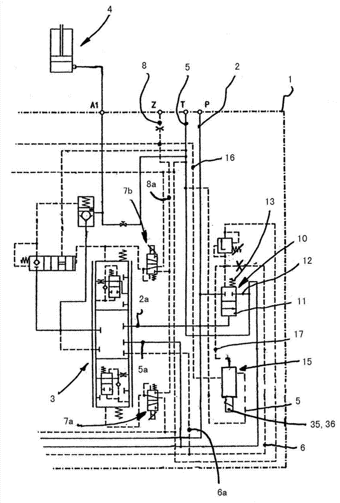
[0023] exist figure 1shows a drive system of a working hydraulic system in the form of a working machine, for example a floor conveyor, construction machine, forestry machine, agricultural machine or utility machine. Shown is a control valve arrangement 1 designed as a control valve block, which is connected at a connection P to the delivery line of a hydraulic pump (not shown in further detail) and at a connection T to the container line leading to the container. The connection P is connected in the control valve arrangement 1 to a delivery line 2 , to which a control directional valve 3 for controlling a consumer 4 of the hydraulic system is connected by means of a delivery branch line 2 a. The connection T is connected in the control valve arrangement 1 to a tank line 5 , to which the control switch valve 3 is connected by means of a tank branch line 5 a. The control directional valve 3 is designed as a load-sensing directional valve, wherein when the control directional v...


PUM


Abstract

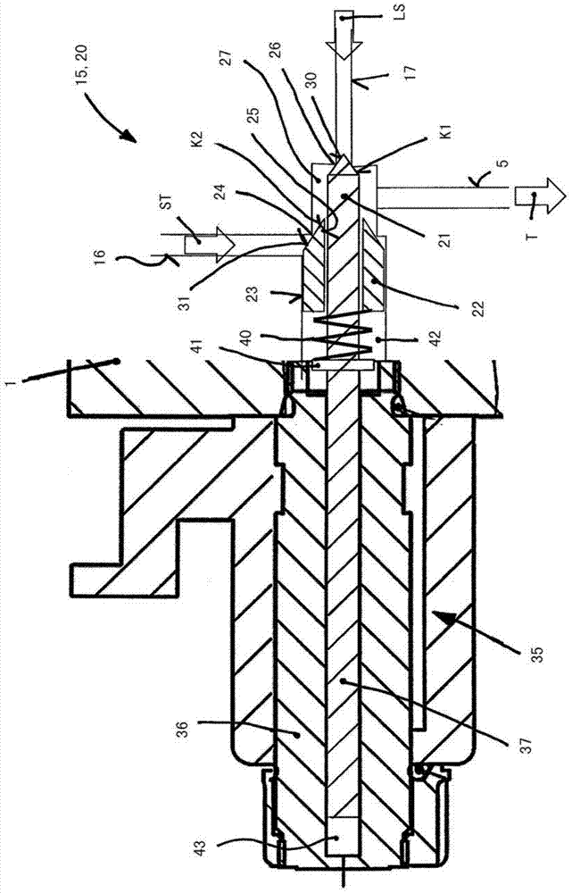
The invention relates to a release valve (15) for a hydrostatic drive system. The release valve controls a control pressure connecting head (ST) and a load pressure connecting head (LS). The release valve has a function position and an unloading position. The release valve is configured to be a double pressure limiting valve (20) having a seat valve structure, and the pressure limiting valve has a first valve seat body (21) used for controlling a valve seat (26) of the load pressure connecting head and a second valve seat body (22) used for controlling valve seat (24) of the control pressure connecting head. A load pressure loading control face (30) stored in the load pressure connecting head is formed on the first valve seat body, and the first valve seat body is loaded onto the unloading position; in the unloading position, the load pressure connecting head unloads to a box connecting head (T). A control pressure loading control face (31) formed in the control pressure connecting head is formed on the second valve seat body, and the second valve seat body is loaded onto an unloading position; on the unloading position, the control pressure connecting head unloads toward the box connecting head.

Description

technical field [0001] The invention relates to a relief valve for a hydrostatic drive system, which actuates a control pressure connection and a load pressure connection, wherein the relief valve has a functional position and an unloading position. Background technique [0002] Such relief valves are used as working hydraulics in load-sensing controlled drive systems of working machines such as land conveyors, construction machines, forestry machines, agricultural machines or utility machines. The release valve is used to release the function of a control directional valve controlling a consumer of the hydraulic power system and is also provided to prevent the consumer from being operated in the event of a disturbance, fault or failure of the drive system and thus to avoid a hazard operating status. [0003] A release valve of this type is known from DE 103 08 910 B4. In order to release the function of the control directional valve controlling the consumer of the hydraul...

Claims


Application Information

Patent Timeline
Patent Type & Authority Applications(China)
IPC IPC(8): F15B20/00F15B13/01F16K17/02F16K17/04
CPCF15B2211/6051F15B13/044F15B13/0405F15B2211/65F15B11/165F15B20/00F15B2211/30535F15B2211/3055F15B2211/355F15B2211/50518F15B2211/575F15B2211/6355F15B2211/863F15B2211/875F16K11/105F16K17/048F16K31/0658
Inventor W·卡拉夫特
Owner LINDE HYDRAULICS
Learn More