Reflective broadband 1/4 wave plate

A reflective, wave plate technology, applied in the direction of optics, instruments, optical components, etc., can solve the problems that cannot meet the broadband application, and achieve the effect of broadband high-efficiency reverse diffraction and high-efficiency diffraction

Inactive Publication Date: 2015-02-04
SHANGHAI UNIVERSITY OF ELECTRIC POWER
View PDF8 Cites 6 Cited by
  • Summary
  • Abstract
  • Description
  • Claims
  • Application Information

AI Technical Summary

Problems solved by technology

The traditional 1 / 4 wave plate utilizes the birefringence properties of anisotropic crystals to provide π / 2 phase retardation between two orthogonal linearly polarized lights. Since the amount of phase retardation is related to the thickness of the wave plate, the traditional wave plate only Can work in a narrower waveband, unable to meet the needs of broadband applications

Method used


Image

  • Reflective broadband 1/4 wave plate
  • Reflective broadband 1/4 wave plate
  • Reflective broadband 1/4 wave plate

Examples


Embodiment

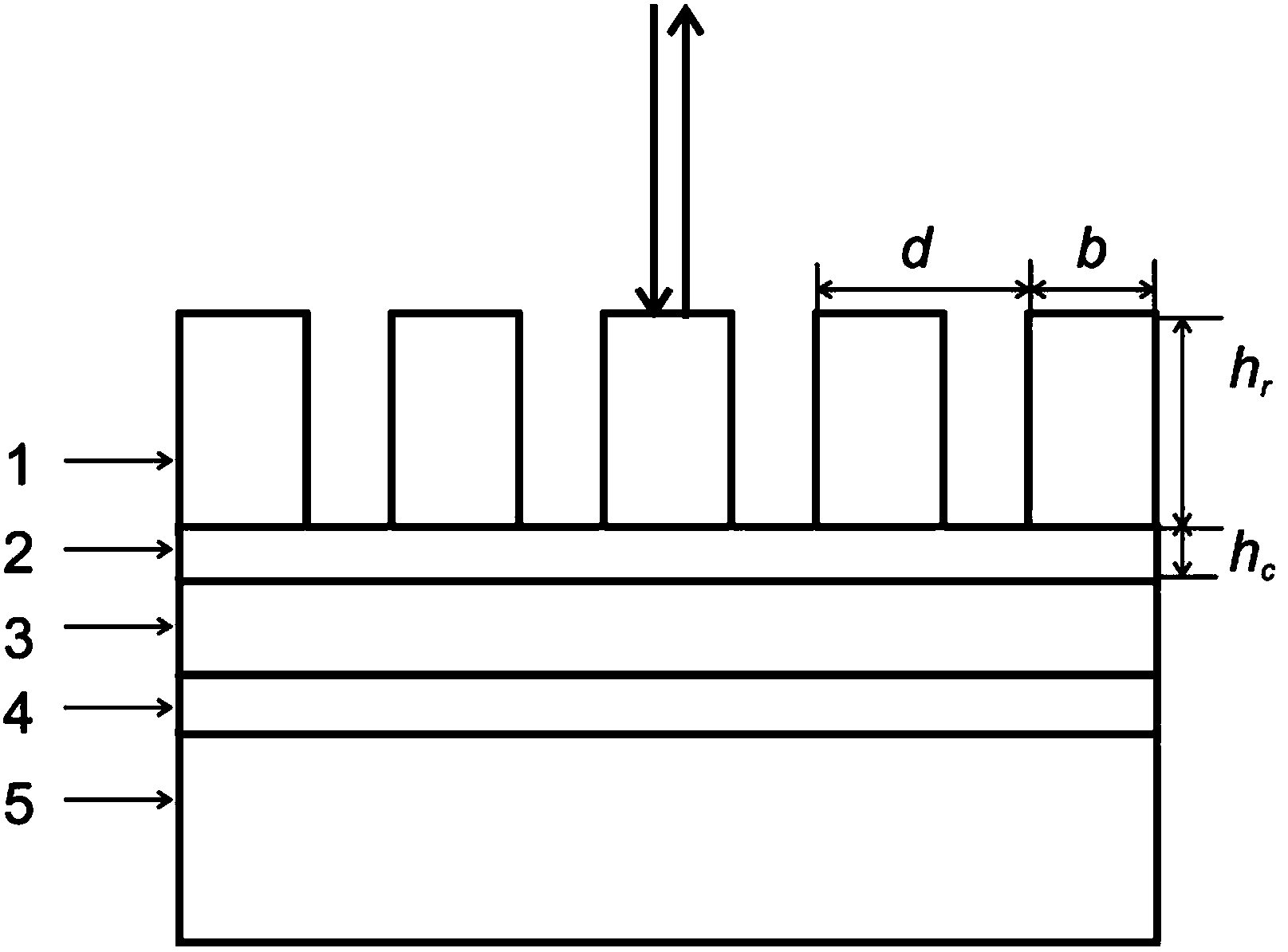
[0020] A broadband reflective wave plate for a central wavelength of 1550 nanometers, its structure is as follows figure 1 As shown, an aluminum oxide film 4, a silver film 3 larger than 100 nanometers, an aluminum oxide film 2 (connection layer) of 61 nanometers, and a silicon oxide film 1 are sequentially coated on the substrate 5, and the silicon oxide film layer 1 etches a rectangular groove grating . The grating period d is 1178-1188 nanometers, and the range of the grating ridge width b can be determined according to the grating period and duty cycle, which is between 300-303 nanometers. In this embodiment, the ridge width is 301.5 nanometers, and the etching depth h r 2517-2527 nm, duty cycle 0.255, connecting layer thickness h c is 61 nm.

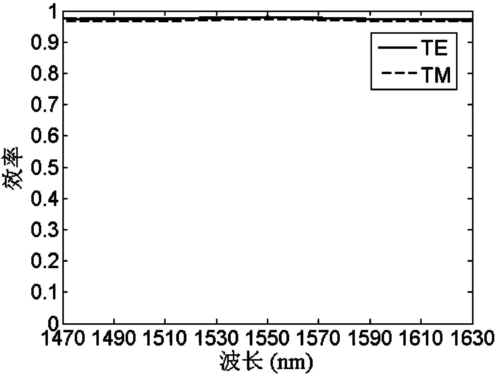
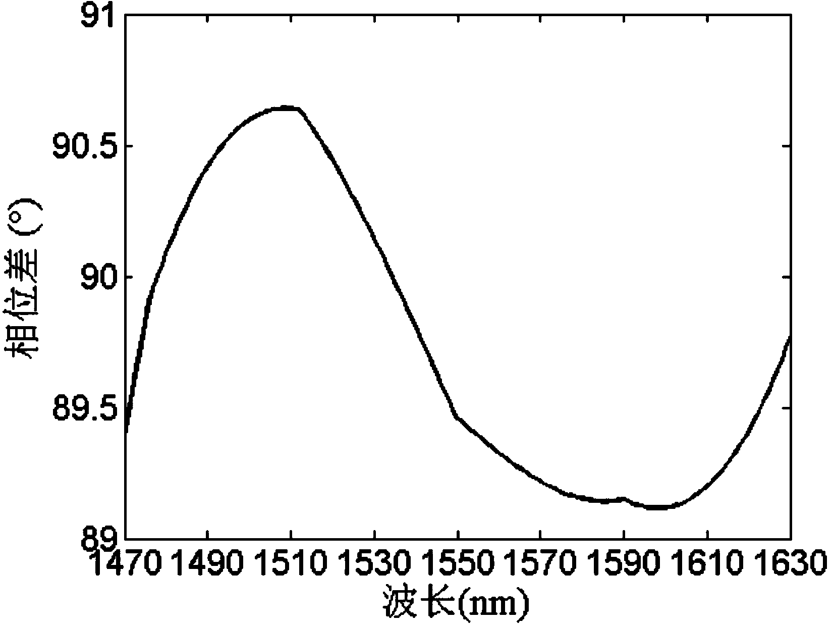
[0021] Table 1 provides a series of specific embodiments applicable to the present invention, wherein: d is the grating period, h r is the grating etching depth, λ is the incident wavelength, η TE is the 0th-order diffraction ef...


PUM


Abstract

The invention relates to a reflective broadband 1/4 wave plate. The reflective broadband 1/4 wave plate comprises a substrate (5); an alumina film (4), a silver film (3), an alumina film (2) and a silicon oxide film (1) are orderly formed on the substrate (5) in a plating way; a rectangular groove grating is etched out in the silicon oxide film (1); the period of the grating is 1178-1188nm, the etching depth is 2517-2527nm, and the duty ratio is 0.255. Compared with the prior art, the reflective broadband 1/4 wave plate can be manufactured by use of the optical holographic recording technology or an electron beam direct writing device in combination with the micro-electronic deep etching process and the coating technology, is highly available in raw materials, low in manufacturing cost, and has important practical prospect.

Description

technical field [0001] The invention relates to a polarization optical component, in particular to a broadband reflective 1 / 4 wave plate. Background technique [0002] In the polarization optical system, the wave plate is used to provide a certain phase delay, so as to realize the control of the polarization state of the light wave. The 1 / 4 wave plate can be used to realize mutual conversion between linearly polarized light and circularly polarized light. The traditional 1 / 4 wave plate utilizes the birefringence properties of anisotropic crystals to provide π / 2 phase retardation between two orthogonal linearly polarized lights. Since the amount of phase retardation is related to the thickness of the wave plate, the traditional wave plate only It can work in a narrower waveband and cannot meet the needs of broadband applications. [0003] Subwavelength gratings have formal birefringence efficiency and can be used to design broadband high-efficiency waveplates. Since reflec...

Claims


Application Information

Patent Timeline
Patent Type & Authority Applications(China)
IPC IPC(8): G02B5/30
CPCG02B5/3083G02B27/286
Inventor 胡安铎初凤红
Owner SHANGHAI UNIVERSITY OF ELECTRIC POWER
Why Eureka
Try Eureka