
Solving light intensity transfer equation-based digital hologram demodulation method

A light intensity transmission equation and digital hologram technology, applied in the field of hologram processing, can solve time-consuming problems and achieve the effect of broad application prospects

Active Publication Date: 2015-02-04
NANJING UNIV OF SCI & TECH
View PDF2 Cites 13 Cited by
  • Summary
  • Abstract
  • Description
  • Claims
  • Application Information

AI Technical Summary

Problems solved by technology

In order to accurately obtain the phase information of the object itself, these aberrations need to be physically or numerically compensated ([2] T.Colomb, F.Montfort, J.Kühn, N.Aspert, E.Cuche, A.Marian, F.Charrière , S.Bourquin, P.Marquet, and C.Depeursinge, "Numerical parametric lens for shifting, magnification, and complete aberration compensation in digital holographic microscopy," J.Opt.Soc.Am.A 23, 3177-3190(2006) .), which is often difficult and time-consuming to manipulate

Method used


Image

  • Solving light intensity transfer equation-based digital hologram demodulation method
  • Solving light intensity transfer equation-based digital hologram demodulation method
  • Solving light intensity transfer equation-based digital hologram demodulation method

Examples


Embodiment

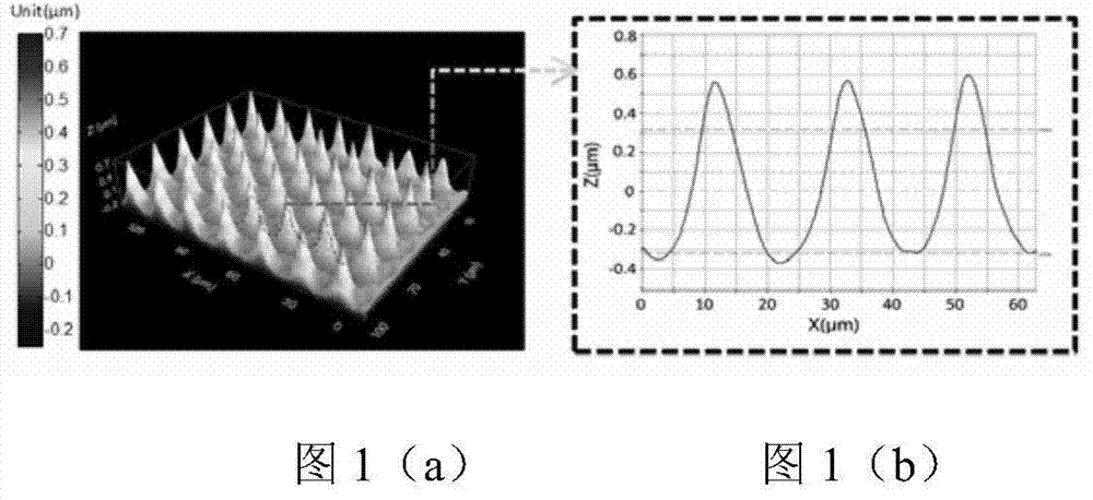
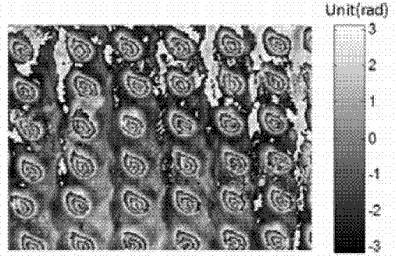
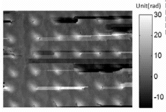
[0059] An embodiment is used below to illustrate the effectiveness of the digital hologram demodulation method based on solving the light intensity transmission equation proposed by the present invention. The sample to be tested is a regular reflective convex array. The array was fabricated on a silicon substrate using laser-induced non-invasive structural processing in a pure oxygen environment at 0.75 atmospheres. The purpose of selecting this sample is to show the robustness of the algorithm of the present invention in complex phase and noise situations. Accurate characterization of the microstructure morphology is crucial for its applications in the fields of integrated optics, microelectromechanical systems, and solar cells. The microstructure can be measured by confocal microscopy or atomic force microscopy, but these methods require a lot of scanning time.

[0060] Figure 1(a) is a topological map measured by confocal microscopy; Figure 1(b) shows a cross-sectional vi...


PUM


Abstract

The invention discloses a solving light intensity transfer equation-based digital hologram demodulation method. The method comprises the following steps of at first, recreating a digital hologram, calculating to obtain complex amplitude distribution on an object plane, normalizing the complex amplitude distribution on the object plane by using amplitude, propagating the normalized complex amplitude for a small distance by using an angular spectrum numerical propagation method to obtain an out-of-focus light intensity image, taking the out-of-focus light intensity image as input data of a solving light intensity transfer equation, and solving the light intensity transfer equation by using a fast Fourier transform-based solving method to obtain phase distribution of an object. By the method, the continuous phase of the object can be directly demodulated from an abaxial hologram, the complex phase unwrapping procedure of the traditional digital hologram is effectively avoided, and tilt aberration introduced by an off-axis structure of an object parameter optical path and secondary phase distortion introduced by an microobjective in the object parameter optical path can also be removed.

Description

technical field [0001] The invention belongs to the hologram processing technology in digital holographic imaging in optical measurement, in particular to a digital hologram demodulation method based on solving light intensity transmission equation. Background technique [0002] Phase recovery is an important topic in optical measurement and imaging technology, and phase imaging technology is playing an important role in both biomedical and industrial detection fields. Especially in the field of biomedical microscopy, optical microscopy has become an indispensable tool in biological and medical research, and is an important basis for the establishment and development of cytology and cell biology. However, due to the low absorption of light waves by most biological cells, it is difficult to achieve clear imaging of cells using ordinary bright-field optical microscopy techniques. On the other hand, the phase distribution of biological cells is very important for the microscop...

Claims


Application Information

Patent Timeline
IPC IPC(8): G06F19/00G03H1/22
Inventor 陈钱左超冯世杰孙佳嵩胡岩陶天阳顾国华张玉珍喻士领张良张佳琳
Owner NANJING UNIV OF SCI & TECH
Learn More