Discrete element analysis method for propagation and damage of coating crack in cutting process of coated cutting tool

A technology of crack propagation and cutting process, applied in special data processing applications, instruments, electrical digital data processing, etc., to achieve the effect of reducing the number of units, the amount of calculation and the calculation time

Inactive Publication Date: 2015-02-11
XIANGTAN UNIV
View PDF2 Cites 4 Cited by
  • Summary
  • Abstract
  • Description
  • Claims
  • Application Information

AI Technical Summary

Problems solved by technology

Judging from the literature that has been mastered, there is no report on the simulation of the cutting process of c

Method used


Image

  • Discrete element analysis method for propagation and damage of coating crack in cutting process of coated cutting tool
  • Discrete element analysis method for propagation and damage of coating crack in cutting process of coated cutting tool
  • Discrete element analysis method for propagation and damage of coating crack in cutting process of coated cutting tool

Examples


Embodiment Construction

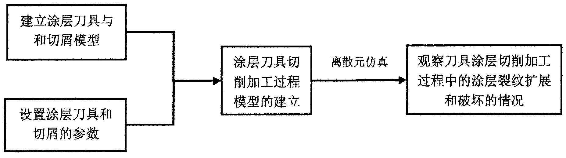
[0027] The present invention will be further described below in conjunction with accompanying drawing.

[0028] A discrete element analysis method for coating crack growth and damage during the cutting process of a coated tool, including: 1 establishment of a discrete element model for the coated tool and chip; 2 setting of the microscopic parameters of the coated tool and chip; 3 coating tool The establishment of the discrete element model of the cutting process; 4. Apply the established discrete element model to simulate and observe the crack growth and damage of the coating during the cutting process of the tool coating.

[0029] The discrete element analysis method of the present invention is as figure 1 shown.

[0030] 1. Establishment of discrete element model of coated tool and chips;

[0031] When using PFC2D software to generate a discrete element model, it usually includes the following three steps:

[0032] 1) In the specified area, by giving porosity, particle p...


PUM


Abstract

The invention discloses a discrete element analysis method for propagation and damage of a coating crack in a cutting process of a coated cutting tool. The discrete element analysis method comprises the following analysis steps of 1) establishing the coated cutting tool and a discrete element model of chips; 2) selecting a suitable contact model and calibrating microscopic parameters of the discrete element model through a mechanical property test; 3) simulating the coated cutting tool and a cutting processing process; 4) observing and recording the conditions of propagation and damage of the coating crack of the coated cutting tool. The discrete element analysis method has the following technical effect that 1, long-distance movement between the coated cutting tool and the chips is simulated by utilizing a method of a periodic boundary; the continuous long chip models are simplified to a periodic flow model of a small section of chips in contact with the coated cutting tool; the number of the units of the chip model is greatly reduced, and the calculated amount and the computation time are greatly reduced; 2, visualization of propagation and damage of the coating crack of the coated cutting tool in a cutting processing process is implemented, through the model states of several time points captured for the cutting processing process of the coated cutting tool, the conditions of propagation and damage of the coating crack of the coated cutting tool in the processing process can be directly observed.

Description

technical field [0001] The invention relates to the coating tool cutting processing technology. Background technique [0002] Carbide-coated cutting tools combine the advantages of high strength, high toughness of the substrate, high hardness and high wear resistance of the coating, and have excellent cutting performance. They are widely used in the machining of difficult-to-machine materials such as superalloys and titanium alloys, especially Play an irreplaceable role in high-speed cutting, dry cutting and other fields. [0003] However, during the cutting process (especially during intermittent cutting), microcracks often appear on the coating part, and macrocracks gradually form under the coupling effect of heat and force, causing local wear and tearing of the coating and even peeling off, which in turn affects its cutting performance and Processing efficiency. During the test, the crack growth and coating damage are often difficult to capture. Therefore, using the nu...

Claims


Application Information

Patent Timeline
IPC IPC(8): G06F17/50
Inventor 姜胜强李添添谭援强张高峰彭锐涛高伟
Owner XIANGTAN UNIV
Why Eureka
Try Eureka