Ion guiding device for mass spectrometer, and collision reaction tank

A collision reaction cell and ion guidance technology, applied in mass spectrometers, dynamic spectrometers, particle separation tubes, etc., can solve the problems of weak ion transmission efficiency and inability to effectively eliminate interference, and achieve simple structure, interference elimination, and good effect. Effect

Inactive Publication Date: 2015-02-11
BEIJING PURKINJE GENERAL INSTR
View PDF12 Cites 5 Cited by
  • Summary
  • Abstract
  • Description
  • Claims
  • Application Information

AI Technical Summary

Problems solved by technology

Quadrupole setups use four electrodes for the best mass discrimination, but less efficient ion transmission than hexapole or octopole setups
The traditional ion guide device includes four, six or eight straight rod-shaped electrode rods with a circular cross-section. The traditional str

Method used


Image

  • Ion guiding device for mass spectrometer, and collision reaction tank
  • Ion guiding device for mass spectrometer, and collision reaction tank
  • Ion guiding device for mass spectrometer, and collision reaction tank

Examples


Embodiment approach 1

[0039] Such as Figure 6A and Figure 6B As shown, the first embodiment of the collision reaction cell of the present invention includes a collision cell 6 and an ion guide device.

[0040] The collision chamber 6 can adopt a conventional structure, has two ion inlets and outlets for ions to enter and exit, and has an air charging port 61, and the number of the air charging port 61 can be one or more. During use, gas such as helium can be filled into the collision chamber 6 through the gas filling port 61 as a collision gas. In this first embodiment, the collision cell 6 is in the shape of a hollow cuboid.

[0041] The ion guide adopts the structure of the present invention, which is installed in the collision chamber 6 . The central through holes of the first insulating seat 1 and the second insulating seat 2 correspond to the two ion entrances and exits of the collision chamber 6 respectively. The ion guide is used to transport ions.

[0042] Such as Figure 7 As shown...

Embodiment approach 2

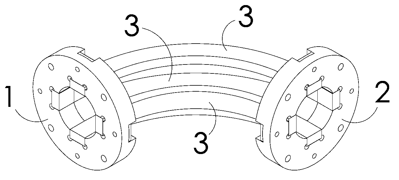
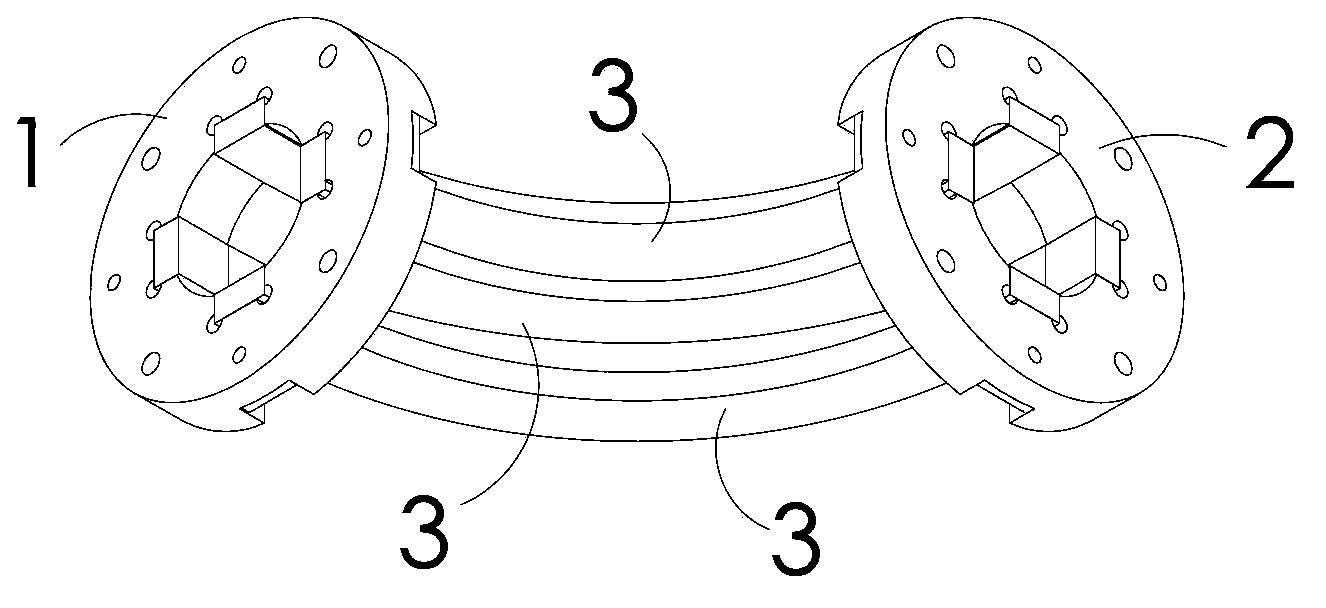
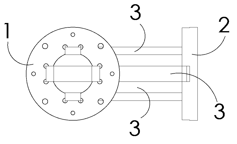
[0049] Such as Figure 8A and Figure 8B As shown, the second embodiment of the collision reaction cell of the present invention differs from the first embodiment only in that:

[0050] The collision chamber 6 is in the shape of a hollow fan-shaped body with a fan-shaped cross section. Further, the curved arc of the arc-shaped electrode rod 3 of the ion guide device is the same as the curved arc of the fan-shaped surface of the collision chamber 6 .

[0051] Other parts of the second embodiment of the collision reaction cell are basically the same as those of the first embodiment, and will not be repeated here.

Embodiment approach 3

[0053] refer to Figure 6A , Figure 6B , Figure 8A and Figure 8B . The third embodiment of the collision reaction cell of the present invention further includes a first ion lens 4 and a second ion lens 5 on the basis of the first embodiment or the second embodiment.

[0054] The first ion lens 4 is located at the front end of the ion guide, close to the ion entrance of the ion guide. The first ion lens 4 can adopt a traditional structure, for example, including 3 electrodes V1, V2, V3, (3 are shown in the figure), 3 Different voltages can be applied to each electrode, and the number of electrodes is not limited to three, and can be appropriately increased or decreased.

[0055] The second ion lens 5 is located at the rear end of the ion guide, close to the exit of the ion guide. The second ion lens includes 3 electrodes V4, V5, V6 (3 shown in the figure), and different voltages can be applied to the 3 electrodes respectively, and the number of electrodes is not limited...


PUM

PropertyMeasurementUnit
Central angleaaaaaaaaaa

Abstract

The invention provides an ion guiding device for a mass spectrometer, and a collision reaction tank. The ion guiding device comprises a first insulating base with a central through hole, a second insulating base with the central through hole, and four electrode posts which are connected between the first insulating base and the second insulating base. The space enclosed by the four electrode posts acts as an ion channel. Shapes of the electrode posts are bent. According to the ion guiding device, interference generated by ions, neutral molecules and photons can be eliminated simultaneously. Besides, the ion guiding device also has the advantages of good mass distinguishing effect and high ion collision efficiency.

Description

technical field [0001] The invention relates to an ion guide device and a collision reaction cell for a mass spectrometer. Background technique [0002] When using ICP-MS (Inductively Coupled Plasma Mass Spectrometer) to determine trace elements or isotope ratios, polyatomic mass spectrometry interference affects the accuracy of the analysis results. In order to eliminate this interference, the commonly used technical means is to introduce a collision reaction cell. The collision reaction cell is a barrel-shaped device arranged between the ion lens and the mass analyzer. pressure state. When the ion beam passes through the collision cell, the polyatomic interfering ions collide or react with the gas, the kinetic energy decreases or the mass number changes, and they are separated from the analysis ions by kinetic energy differentiation (KED) or mass differentiation (MD). [0003] In order to constrain the trajectory of ions in the collision chamber, an ion guide device con...

Claims


Application Information

Patent Timeline
IPC IPC(8): H01J49/04H01J49/02H01J49/42
CPCH01J49/063
Inventor 张小华凌星张华商颖健
Owner BEIJING PURKINJE GENERAL INSTR
Why Eureka
Try Eureka