Electric fuse structure
An electric fuse and fuse technology, applied in circuits, electrical components, electric solid devices, etc., can solve the problems of long electric fuse length, large integrated circuit chip area, and metal interconnection layout design restrictions, etc. small area effect
- Summary
- Abstract
- Description
- Claims
- Application Information
AI Technical Summary
Problems solved by technology
Method used
Image
Examples
no. 1 example
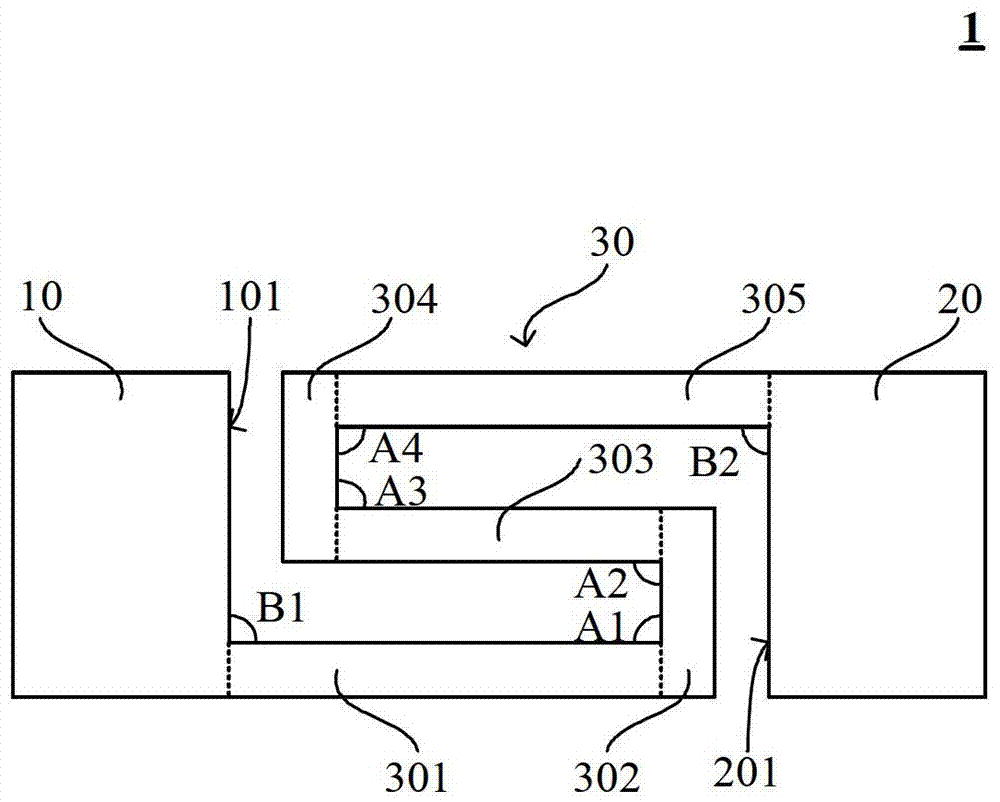
[0036] like figure 2 As shown, the electric fuse structure 1 of this embodiment includes: an electric fuse 30, and the electric fuse 30 includes five sub-fuses connected end to end, and the five sub-fuses are respectively: sub-fuses 301, sub-fuses 302, A sub-fuse 303, a sub-fuse 304, and a sub-fuse 305; an anode 10 and a cathode 20 respectively located at both ends of the electric fuse 30 and connected to the electric fuse 30, the anode 10 has a first front 101 facing the cathode 20, The cathode 20 has a second front 201 facing the anode 10, the first front 101 is parallel to the second front 201, and the facing area of the first front 101 and the second front 201 is equal to the area of the first front 101 and the area of the second front 201. area. in:
[0037] The sub-fuse 301 is connected to the first front surface 101 of the anode 10, and the angle B1 between the two is 90 degrees; the sub-fuse 301 is connected to the sub-fuse 302, and the angle A1 between the tw...
no. 2 example
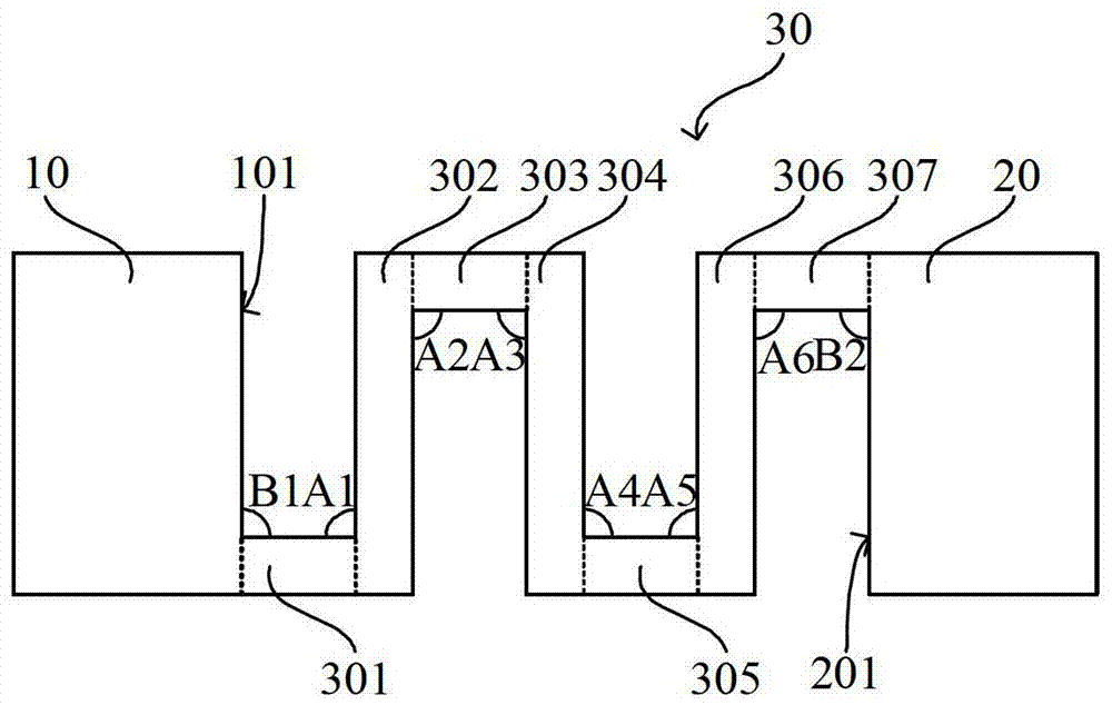
[0043] The difference between the second embodiment and the first embodiment is: as image 3 As shown, the electric fuse 30 includes seven segments of sub-fuse connected end to end. Fuse 306, sub-fuse 307. in:
[0044]The sub-fuse 301 is connected to the first front surface 101 of the anode 10, and the angle B1 between the two is 90 degrees; the sub-fuse 301 is connected to the sub-fuse 302, and the angle A1 between the two is 90 degrees; The sub-fuse 302 is connected to the sub-fuse 303, and the angle A2 between the two is 90 degrees; the sub-fuse 303 is connected to the sub-fuse 304, and the angle A3 between the two is 90 degrees; the sub-fuse 304 It is connected to the sub-fuse 305, and the angle A4 between the two is 90 degrees; the sub-fuse 305 is connected to the sub-fuse 306, and the angle A5 between the two is 90 degrees; the sub-fuse 306 and the sub-fuse 307 The sub-fuse 307 is connected to the second front surface 201 of the cathode 20, and the angle B2 between th...
no. 3 example
[0048] The difference between the third embodiment and the first embodiment is: as Figure 4 As shown, the electric fuse 30 includes seven segments of sub-fuse connected end to end. Fuse 306 , sub-fuse 307 ; in addition, the anode 10 has a first side 102 connected to the first front 101 , and the cathode 20 has a second side 202 connected to the second front 201 . in:
[0049] The sub-fuse 301 is connected to the first side 102 of the anode 10, and the angle B1 between the two is 90 degrees; the sub-fuse 301 is connected to the sub-fuse 302, and the angle A1 between the two is 90 degrees; The sub-fuse 302 is connected to the sub-fuse 303, and the angle A2 between the two is 90 degrees; the sub-fuse 303 is connected to the sub-fuse 304, and the angle A3 between the two is 90 degrees; the sub-fuse 304 It is connected to the sub-fuse 305, and the angle A4 between the two is 90 degrees; the sub-fuse 305 is connected to the sub-fuse 306, and the angle A5 between the two is 90 deg...
PUM
 Abstract
Description
Claims
Application Information
 - R&D
- Intellectual Property
- Life Sciences
- Materials
- Tech Scout
- Unparalleled Data Quality
- Higher Quality Content
- 60% Fewer Hallucinations
Browse by: Latest US Patents, China's latest patents, Technical Efficacy Thesaurus, Application Domain, Technology Topic, Popular Technical Reports.
© 2025 PatSnap. All rights reserved.Legal|Privacy policy|Modern Slavery Act Transparency Statement|Sitemap|About US| Contact US: help@patsnap.com


