Side flow denitrification tank and side flow denitrification method

A technology of denitrification and secondary settling tank, which is applied in chemical instruments and methods, anaerobic digestion treatment, water/sludge/sewage treatment, etc., can solve the problems affecting the denitrification effect of the system, increase power consumption, etc., and achieve improved denitrification Effect of Phosphorus, Reduced Dilution, Enhanced Treatment Capacity and Treatment Efficiency

Active Publication Date: 2015-02-18
THUNIP CORP LTD +1
View PDF5 Cites 2 Cited by
  • Summary
  • Abstract
  • Description
  • Claims
  • Application Information

AI Technical Summary

Problems solved by technology

However, because the anaerobic zone is in the front, the nitrate in the return sludge will have an adverse effect on the anaerobic zone; since the anoxic zone is located in the middle of the system, denitrification is at a disadvantage in the distribution of carbon sources, thus affecting the denitrification of the system Effect; in order to reduce the nitrate in the return sludge, it is necessary to increase the return flow of the mixed liquid, and the increase of the return flow will inevitably increase the power consumption

Method used


Image

  • Side flow denitrification tank and side flow denitrification method
  • Side flow denitrification tank and side flow denitrification method
  • Side flow denitrification tank and side flow denitrification method

Examples


Embodiment 1

[0037] Example 1: Combination of side stream denitrification tank and AAO process

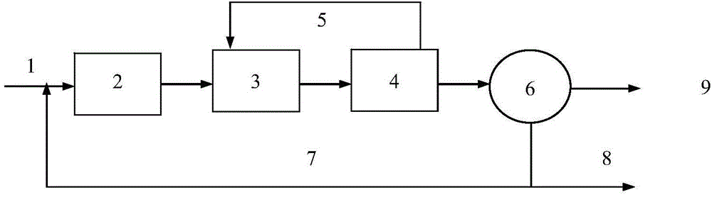
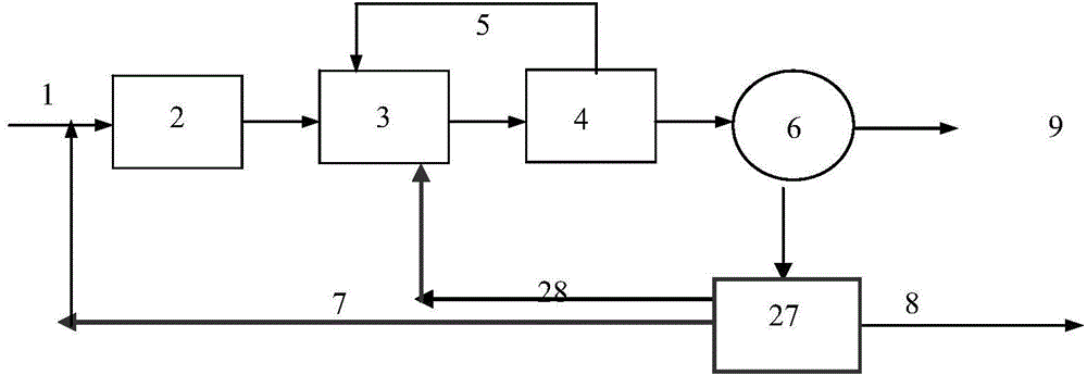
[0038] The equipment combining side stream denitrification tank with AAO process, see figure 2 and Figure 5, including the reaction tank grid used as anaerobic zone 2, anoxic zone 3, aerobic zone 4 and secondary sedimentation tank 6, anaerobic zone 2, anoxic zone 3, aerobic zone 4 and secondary sedimentation tank 6 pass through the pipeline in sequence Connection, the aerobic zone 4 and the anoxic zone 3 are connected through the mixed liquid return pipe 5 .

[0039] The bottom of the secondary settling tank 6 is connected to the middle of the bottom of the side flow denitrification tank 27 through the mud inlet pipe 10, and the side of the side flow denitrification tank near the inlet of the mud inlet pipe is provided with a slant plate 12, and the slant plate 12 is supported by a slant plate edge bracket 15 , the edge support 15 of the inclined plate is fixed on the inner wall of the pool...

Embodiment 2

[0043] Example 2: Combination of side stream denitrification sewage treatment method and AAO process

[0044] Inlet flow is 40000m 3 / day, the influent water quality is:

[0045] BOD5≤160mg / L; CODcr≤300mg / L; SS≤180mg / L; TN≤45mg / L; NH 3 -N≤35mg / L; TP≤4mg / L.

[0046] Using the side flow denitrification tank of embodiment 1, the sewage to be treated is treated according to the AAO biochemical reaction process, first enters the anaerobic zone 2, and then enters the anoxic zone, the aerobic zone and the secondary sedimentation tank for treatment, and the secondary sedimentation tank is discharged The mud side flow enters the sludge denitrification tank, and the residence time is 1 hour. The nitrate concentration entering the side flow denitrification tank is 15 mg / L, and the sludge concentration entering is 8000 mg / L (water content 99.2%). The sludge concentration out of the mud denitrification tank is 18000mg / L, and the nitrate concentration is 3mg / L. The sludge after endogeno...

Embodiment 3

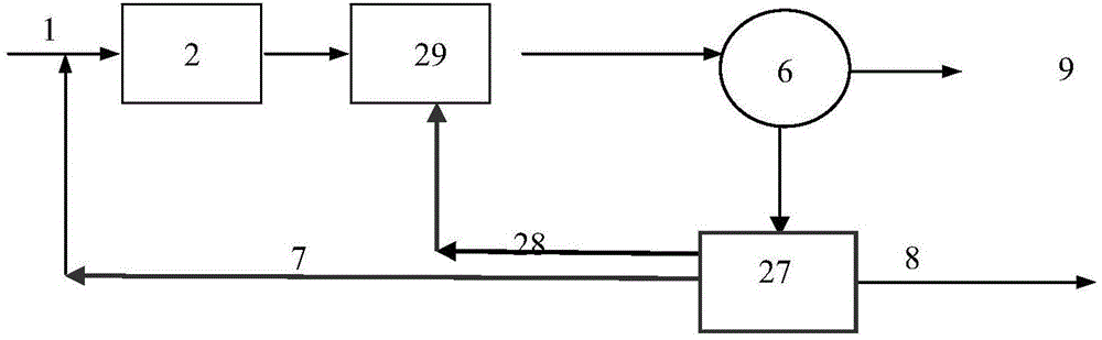
[0051] The effluent has reached the first-level A standard of the national "Urban Sewage Treatment Plant Pollutant Discharge Standard". Example 3: Combination of Side Stream Denitrification Sewage Treatment Method and Oxidation Ditch Process

[0052] Inlet flow is 30000m 3 / day, the influent water quality is:

[0053] BOD5≤180mg / L; CODcr≤330mg / L; SS≤190mg / L; TN≤40mg / L; NH 3 -N≤30mg / L; TP≤3mg / L.

[0054] see image 3 , using the side flow denitrification tank of embodiment 1, the sewage to be treated first enters the anaerobic zone 2, then enters the oxidation ditch 29 and the secondary sedimentation tank for processing, and the side flow of the sludge from the secondary sedimentation tank enters the sludge denitrification tank, The residence time is 1.5 hours, the nitrate concentration entering the side stream denitrification tank is 15mg / L, the sludge concentration entering is 8500mg / L, the sludge concentration flowing out from the sludge denitrification tank is 17000mg / L...


PUM


Abstract

The invention relates to a side flow denitrification technique which can be used in combination with an AAO (anaerobic-anoxic-oxic) technique, a CAST (cyclic activated sludge technology) technique, an oxidation ditch technique with a front end anaerobic region and any other activated sludge treatment technique. When the technique is used in combination with the AAO technique, a sludge discharge pipe of a secondary sedimentation tank is connected with a side flow denitrification tank, the upper part of the side flow denitrification tank is connected with a supernate pipe, and the supernate pipe is connected with an anoxic zone and the secondary sedimentation tank. When the technique is used in combination with the oxidation ditch technique with a front end anaerobic region, a sludge discharge pipe of a secondary sedimentation tank is connected with a side flow denitrification tank, and the upper part is connected with a supernate pipe which is connected with an oxidation ditch and the secondary sedimentation tank. When the technique is used in combination with the CAST technique, a sludge discharge pipe of a main reaction region is connected with a side flow denitrification tank, and a supernate pipe is connected with the main reaction region. The side flow denitrification tank provided by the invention enhances the sludge concentration, and the sludge is subjected to endogenous respiration denitrification, thereby greatly lowering the nitrate amount, reducing the influence of the sludge on the anaerobic section of the biochemical reaction tank or the phosphorus release of the biological selection region of the CAST technique, and enhancing the dephosphorization effect of the system.

Description

technical field [0001] The invention relates to a side flow denitrification process, which belongs to the technical field of sewage treatment. Background technique [0002] In the existing sewage treatment technology, the commonly used sewage nitrogen and phosphorus removal process is the AAO process, which is a synchronous phosphorus and nitrogen removal process developed on the anaerobic-anoxic process in the 1970s. The biological reaction tank is composed of anaerobic, Anoxic and aerobic three-stage composition, the typical process see figure 1 . This is a plug-flow pre-denitrification process, which is characterized by three stages of anaerobic, anoxic, and aerobic stages with clear functions and clear boundaries. The three stages can be artificially created and controlled according to the water inlet conditions and water outlet requirements. The time-space ratio and operating conditions can achieve a relatively high denitrification rate according to needs. [0003] C...

Claims


Application Information

Patent Timeline
Patent Type & Authority Applications(China)
IPC IPC(8): C02F9/14C02F3/28
CPCC02F3/2866C02F3/305Y02E50/30
Inventor 周丽颖李星文
Owner THUNIP CORP LTD
Why Eureka
Try Eureka