Column loudspeaker with built-in phase inversion device

A sound column and phase inversion technology, applied in the field of built-in phase-inverted compression audio systems, can solve the problems of inability to achieve multi-frequency output, lack of three-dimensional sound effects, blurred bass, etc., to achieve a wide stereo effect, good instant response, Eliminates the effects of box shock and standing waves

Inactive Publication Date: 2015-02-18
林伟健
View PDF5 Cites 2 Cited by
  • Summary
  • Abstract
  • Description
  • Claims
  • Application Information

AI Technical Summary

Problems solved by technology

The low-frequency sound reproduced by the speaker is still unsatisfactory. Relying on the resonance of the square box and the setting of the cylindrical inverter tube, the low frequency has only one tone, and the bass is indistinct; Allow limited frequencies to pass through, the sound effect often lacks stereoscopic effect, and there is not enough width in the bass to achieve multi-frequency output

Method used


Image

  • Column loudspeaker with built-in phase inversion device
  • Column loudspeaker with built-in phase inversion device
  • Column loudspeaker with built-in phase inversion device

Examples


Embodiment 1

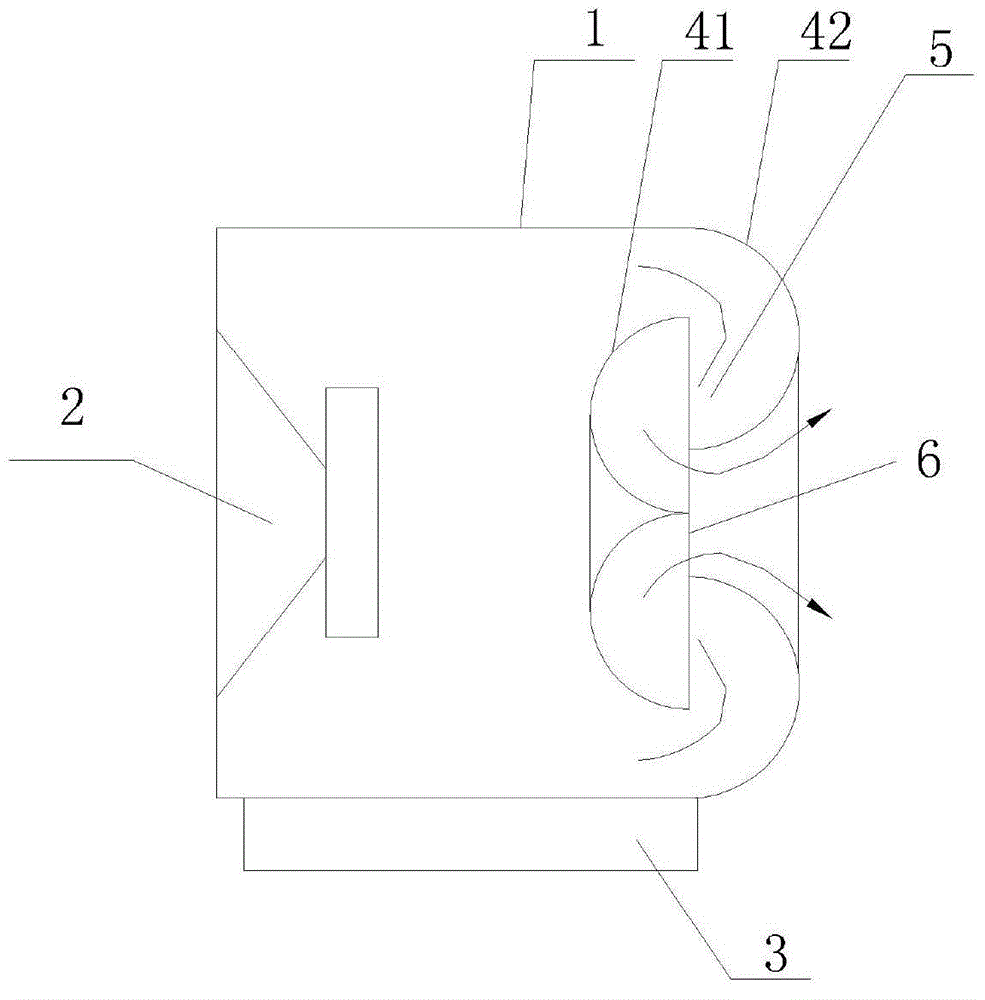
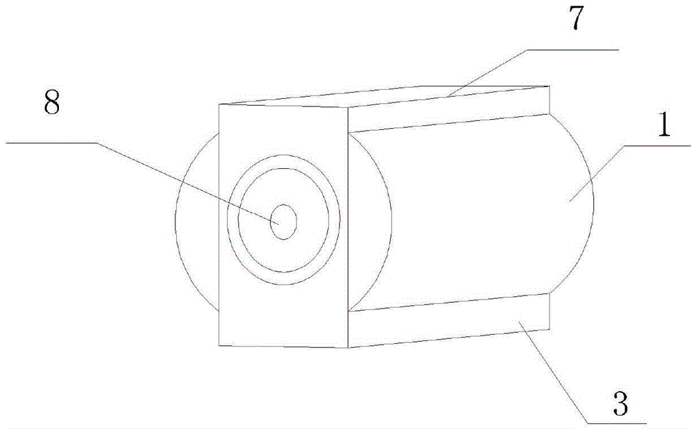
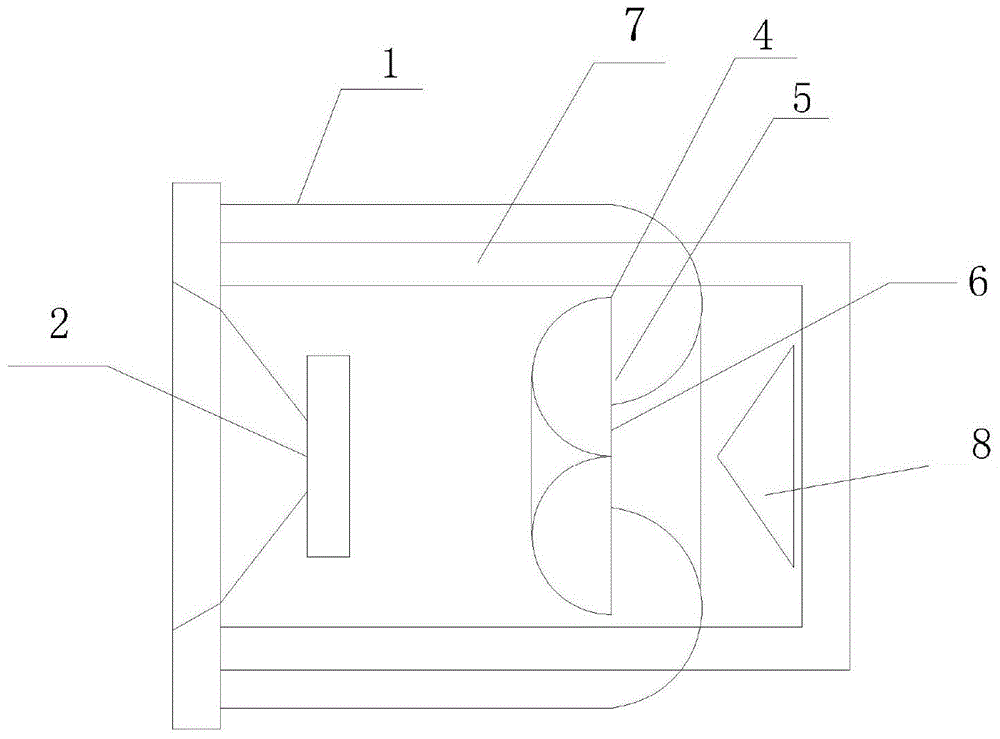
[0018] Such as Figure 1-3 As shown, the sound column of the built-in inverter device of the present invention is mainly composed of a cylindrical casing 1, a speaker 2 on the left side of the casing 1, and a base 3 under the casing 1. The speaker includes a magnet and a paper disc, and the cylindrical casing The other side opposite to the speaker magnet in the body cavity is provided with an airflow bypass device 4, which is coaxial with the horn, and it includes relatively coaxial inner and outer flow covers (41, 42), and the inner and outer flow covers (41 , 42) The connection constitutes two symmetrical S-shaped airflow passages 5; the horn 2 and the airflow bypass device 4 are relatively arranged on both sides in the cylindrical housing 1, and a gap is provided between the two. The inner flow cover 41 is mainly composed of two hemispherical covers joined together, a conical groove is arranged in the middle, and the end of the conical groove is connected with the outer flo...

Embodiment 2

[0021] The external audio amplifier can also be replaced by a horn, that is, a horn is connected to the outer cover, and one end of the horn is arranged outside the outer flow cover to cover the outer flow cover at intervals, and the other end is bent and connected to the cylindrical shell. The sound wave is processed internally without reverberation tailing. It is directly sent to the horn for amplification by inverting the phase at 180° internally, and coincides with the sound wave on the front of the cone, which achieves the design purpose; since the sound speed is 344m / s, the sound comes out from the back of the speaker, to Piston-type airflow advances, and then reverses the internal phase by 180°, the horn is enlarged, the rear wall bounces, and finally coincides with the front sound wave. The whole process is only about 1m away, and there will be no abnormal noise.

[0022] Through the above implementation method, it is known that in the cylinder, the sound phase differen...


PUM


Abstract

The invention discloses a column loudspeaker with a built-in phase inversion device. The column loudspeaker comprises a cylindrical housing, a loudspeaker body, a sounding releasing hole and a base. The column loudspeaker is characterized in that a flow streaming device is arranged on one side of the cylindrical housing corresponding to the loudspeaker body coaxially; a streaming cover includes an inner streaming cover and an outer streaming cover which are coaxial and which are provided with adjacent connected openings; the connection of the inner and outer streaming covers is provided with two symmetrical wave-shaped groove air flow channels; the loudspeaker body and the flow streaming device are arranged on two inner sides of the cylindrical housing at intervals correspondingly; the cylindrical housing is further provided with a frame, one end of the frame is connected to the base fixing the loudspeaker body, and the other end is provided with a conical audio diffuser. The column loudspeaker has the advantages of novel structure, multiple frequency output and fine sound quality.

Description

technical field [0001] The invention belongs to the field of audio electroacoustics, in particular to a surround-type built-in inverted compression sound system. Background technique [0002] At present, common speakers mainly include closed boxes, reflection boxes, transmission lines, coupling cavities and speakers, etc., extending to both ends in the frequency range, and the upper end of the high frequency is mainly obtained by applying small-caliber lightweight diaphragms and other methods. Solved, but the reproduction of the lower end of the low frequency still needs the help of a bulky box cavity. The low-frequency sound reproduced by the speaker is still unsatisfactory. Relying on the resonance of the square box and the setting of the cylindrical inverter tube, the low frequency has only one tone, and the bass is indistinct; Allowing limited frequencies to pass through, the sound effect often lacks three-dimensionality, and there is not enough width in the bass to ach...

Claims


Application Information

Patent Timeline
Patent Type & Authority Applications(China)
IPC IPC(8): H04R1/20
Inventor 林伟健
Owner 林伟健
Why Eureka
Try Eureka