A sewage treatment device based on mechanical recompression technology

A sewage treatment device and mechanical recompression technology, applied in water/sewage treatment, heating water/sewage treatment, water/sludge/sewage treatment, etc., can solve the problem of unable to automatically adjust the motor speed, unable to realize unattended operation, Operators require high difficulty and other issues to achieve the effect of sewage treatment, convenient expansion, and strong operability

Active Publication Date: 2017-07-11
中船重工信息科技有限公司
View PDF6 Cites 0 Cited by
  • Summary
  • Abstract
  • Description
  • Claims
  • Application Information

AI Technical Summary

Problems solved by technology

[0005] The main disadvantages are: 1. It is difficult for the operator to master the necessary experience and technology;
[0006] 2. It is easy to cause system failure due to operational errors;
[0007] 3. The motor speed cannot be automatically adjusted, resulting in energy waste;
[0008] 4. Unattended operation cannot be realized

Method used


Image

  • A sewage treatment device based on mechanical recompression technology
  • A sewage treatment device based on mechanical recompression technology
  • A sewage treatment device based on mechanical recompression technology

Examples


Embodiment 1

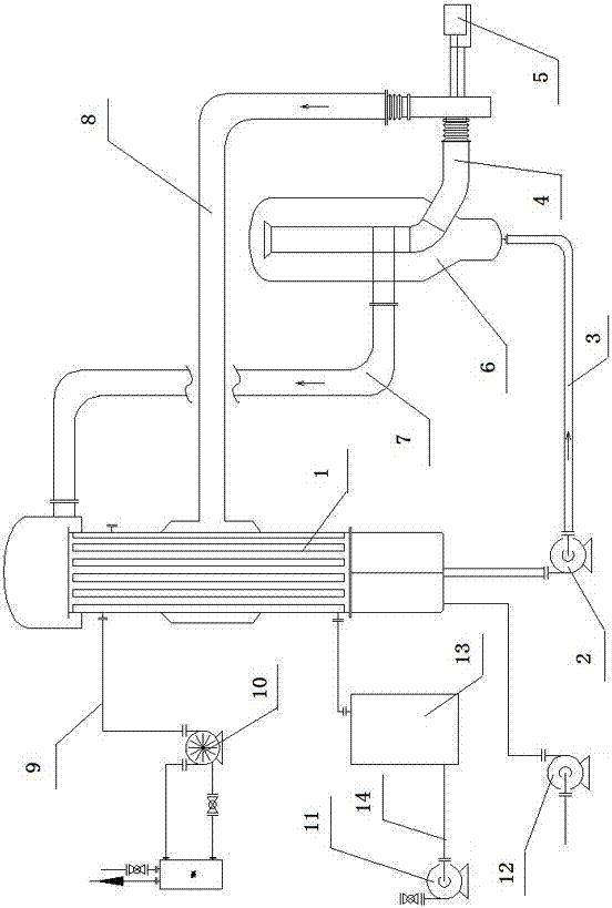
[0035] Embodiment 1, with reference to figure 1 -2. A sewage treatment device based on mechanical recompression technology:

[0036] The device includes a separator 6, an evaporation heat exchanger 1, a circulation pump 2, a feed pump 12, a vacuum pump 10, a compressor 5 and a condensate pump 11; the bottom of the evaporation heat exchanger 1 is connected with the evaporation heat exchanger 1 The feed pipeline connected by the tube side, the feed pump 12 is arranged on the feed pipeline; the liquid circulation pipeline 3 is arranged between the evaporation heat exchanger 1 and the bottom of the separator 6, and the circulation pump 2 is arranged on the liquid circulation pipeline 3 Above; the compressor 5 is connected to the gas supply pipeline 8, the other end of the gas supply pipeline 8 is connected to the middle part of the evaporative heat exchanger 1, and the upper part of the evaporative heat exchanger 1 is connected to the liquid return pipeline 7 before the separator ...

Embodiment 2

[0039] Embodiment 2, in the sewage treatment device based on mechanical recompression technology described in Embodiment 1: a condensation water tank 13 is also provided on the condensation pipeline 14 .

Embodiment 3

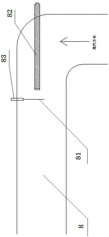
[0040] Embodiment 3, in a sewage treatment device based on mechanical recompression technology described in Embodiment 1 or 2: a negative pressure detection device is provided on the gas supply pipeline 8; the negative pressure detection mechanism is installed on the pipe elbow It is composed of a proximity switch 82, a blocking plate 81 and a fixing device 83; the proximity switch 82 is installed facing the steam direction, and the blocking plate 81 is fixedly installed on the side of the proximity switch 82 by the fixing device 83.


PUM


Abstract

The invention relates to a sewage treatment plant based on mechanical recompression technique, which comprises a separator, an evaporation heat exchanger, a circulating pump, a feed pump, a vacuum pump, a compressor and a condensate pump. The sewage treatment plant is also provided with a control system, wherein the control system comprises a PLC (programmable logic controller) control station; the PLC control station is connected with a touch screen and an I / O expansion module through control lines; and the I / O expansion module is respectively connected with a steam regulating valve, the circulating pump, the compressor, the condensate pump, a feed regulating valve of the feed pump and a vacuum regulating valve of the vacuum pump through signal lines. The sewage treatment plant has the advantages of reasonable structural design and high operability, and can effectively implement sewage treatment. The sewage treatment plant can automatically regulate the motor frequency and feed rate according to the evaporation capacity, thereby implementing unmanned control state in deed and automatic control, and achieving the goals of energy saving and emission reduction by dynamic equilibrium, frequency autoregulation and other techniques.

Description

technical field [0001] The invention relates to a sewage treatment device, in particular to a sewage treatment device based on mechanical recompression technology. Background technique [0002] At present, the mechanical vapor recompression sewage treatment control system mainly deals with the industrial wastewater discharged from chemical plants. At present, the common processing devices and devices all need to consume a huge amount of energy, which is not conducive to energy saving. At present, it is necessary to develop high-efficiency, low-pollution evaporation treatment technology. [0003] Mechanical steam recompression is to recompress the single-effect evaporated steam through the compressor, increase the temperature and pressure, increase the heat enthalpy, and then enter the heat exchanger to condense to make full use of the latent heat of the steam. This kind of technology in China belongs to the emerging sunrise industry. Many factories and mines need MVR syste...

Claims


Application Information

Patent Timeline
Patent Type & Authority Patents(China)
IPC IPC(8): C02F1/04
CPCC02F1/041
Inventor 咸云飞周军朱丽颜耀田亚丽赵媛媛吴茂传居世钊李丁董奇王洪葛磊李建华骆伟李闻
Owner 中船重工信息科技有限公司
Why Eureka
Try Eureka