Rotating wheel non-contact excitation type fluid kinetic energy conversion device

A technology of kinetic energy conversion and rotating wheels, which is applied in the direction of engines, wind power generation, engine components, etc., can solve the problems of complex mechanical structures, short service life, structural fatigue damage, etc., and achieve the effect of flexible installation methods

Active Publication Date: 2015-02-25
HARBIN INST OF TECH
View PDF6 Cites 12 Cited by
  • Summary
  • Abstract
  • Description
  • Claims
  • Application Information

AI Technical Summary

Problems solved by technology

[0007] The present invention aims to solve the problems that existing fluid kinetic energy conversion devices are difficult to adapt to complex fluid environments, complex mechanical structures, low energy capture efficiency, difficult to realize miniaturization and portability, prone to structural fatigue damage and short service life, and further provides A rotating wheel non-contact excitation type fluid kinetic energy conversion device

Method used


Image

  • Rotating wheel non-contact excitation type fluid kinetic energy conversion device
  • Rotating wheel non-contact excitation type fluid kinetic energy conversion device
  • Rotating wheel non-contact excitation type fluid kinetic energy conversion device

Examples


specific Embodiment approach 1

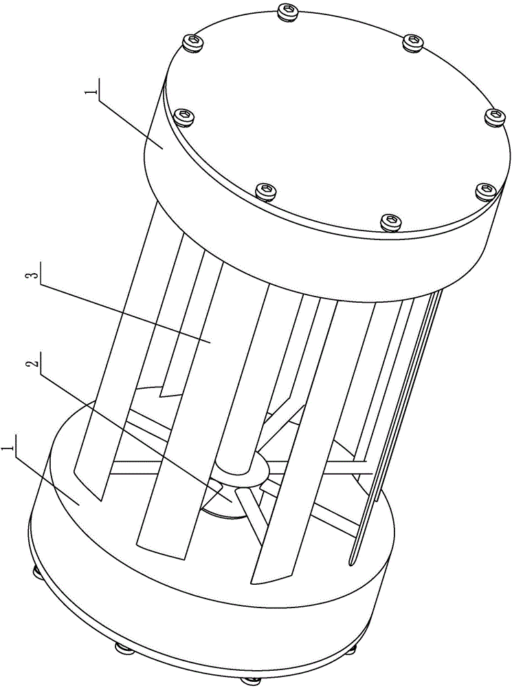
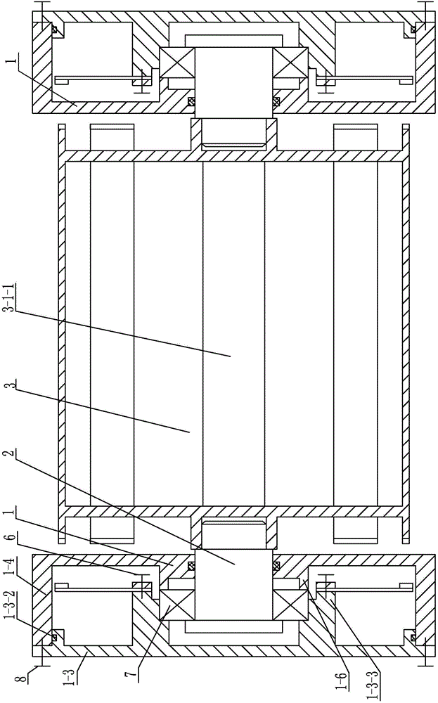
[0018] Specific implementation mode one: combine Figure 1-Figure 8 Explain that the rotating wheel non-contact excitation fluid kinetic energy conversion device of this embodiment includes a rotating wheel 3, two sets of fixed bases 1, two wheel axles 2, 2N excited magnet pieces 4 and 2N excited magnet pieces 5; Where N is a positive integer, and N≥8;

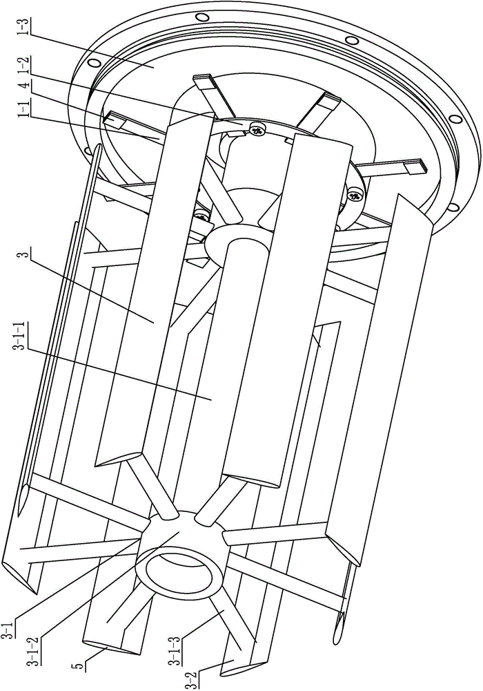
[0019] The rotating wheel 3 includes a support shaft frame 3-1 and N wheel plates 3-2;

[0020] Each fixed base 1 includes a barrel-shaped casing 1-4, a neck flange base 1-3 and N piezoelectric composite cantilever beams 1-1, and the middle part of the bottom of the barrel-shaped casing 1-4 is processed There are through holes 1-5;

[0021] Each piezoelectric composite cantilever beam 1-1 includes a metal elastic plate 1-1-1 and two piezoelectric ceramic sheets 1-1-2, and one end of each metal elastic plate 1-1-1 is installed on a flange with a neck On the end face of the neck 1-3-3 of the base 1-3, the length direction of ...

specific Embodiment approach 2

[0025] Specific implementation mode two: combination Figure 7 and Figure 8 Note that the number of piezoelectric composite cantilever beams 1 - 1 in this embodiment is eight. Such arrangement satisfies the requirement of effective conversion from vibration energy to electric energy. Others are the same as in the first embodiment.

specific Embodiment approach 3

[0026] Specific implementation mode three: combination Figure 8 Note that each metal elastic plate 1-1-1 in this embodiment is a phosphor bronze elastic plate. In this way, the phosphor bronze has good elasticity, wear resistance and fatigue resistance, and is easy to use. Others are the same as in the first or second embodiment.


PUM


Abstract

The invention relates to an energy conversion device, in particular to a rotating wheel non-contact excitation type fluid kinetic energy conversion device. The device solves the problems that an existing fluid kinetic energy conversion device cannot easily adapt to a complex fluid environment, and is complex in mechanical structure, low in energy harvesting efficiency, hard to become micro or portable, prone to structural fatigue failure and short in service life. The device comprises a rotating wheel, two fixing bases, two rotating shafts, 2N excited magnet pieces and 2N excitation magnet pieces. The rotating wheel comprises a supporting shaft frame and N wheel plates. Each fixing base comprises a cylindrical housing, a hubbed flange base and N piezoelectric composite cantilever beams. Each piezoelectric composite cantilever beam comprises an elastic metal plate and two piezoelectric ceramic plates. The cylinder wall of the cylindrical housing and the base plate of the hubbed flange base of each fixing base are connected into a whole. The rotating wheel non-contact excitation type fluid kinetic energy conversion device is used in the field of new energy power generation.

Description

technical field [0001] The invention relates to an energy conversion device, which belongs to the field of new energy power generation devices. Background technique [0002] With the rapid development of integrated circuit design and manufacturing technology, the miniaturization and miniaturization of electronic components has become a trend, and low energy consumption design technology has also made the power consumption of these electronic components smaller and smaller. As a typical example of this type of electronic components, wireless sensors are commonly found in electromechanical systems such as modern logistics equipment, flexible production lines, and signal transfer stations. They are especially common in occasions where the environment is relatively complex and unsuitable for manual operation. The energy supply requirements of such devices are The system is stable, reliable, and low in installation and maintenance costs. The low-energy power supply of traditiona...

Claims


Application Information

Patent Timeline
Patent Type & Authority Applications(China)
IPC IPC(8): H02N2/18F03B13/00F03D9/00
CPCY02E10/72
Inventor 陈维山董帝渤郝亚强石胜君刘军考侯珍秀
Owner HARBIN INST OF TECH
Why Eureka
Try Eureka