Automatic phase selection control valve

A technology for phase selection and valve control, which is applied in wellbore/well valve devices, production fluids, wellbore/well components, etc., and can solve problems such as the inability to fully utilize the advantages of horizontal wells, the rapid rise of water cut, and the waste of resources. , to achieve the effect of improving the balance control effect, eliminating the influence of the annular flow, and eliminating the toe and heel effect.

Active Publication Date: 2015-03-04
SOUTHWEST PETROLEUM UNIV
View PDF6 Cites 16 Cited by
  • Summary
  • Abstract
  • Description
  • Claims
  • Application Information

AI Technical Summary

Problems solved by technology

The development of horizontal wells is to increase oil well production and economic benefits of oil field development by expanding the drainage area of ​​oil layers. Since the horizontal section is very long, when developing a homogeneous and single oil layer, the existence of wellbore friction and unbalanced pressure difference makes the two ends of the horizontal section The high liquid production intensity and the low intermediate liquid production intensity lead to very unbalanced contribution rate of each section of the horizontal well. As the production time goes by, the funnel effect of the horizontal well becomes more and more obvious, and a water ridge or Gas ridges cause bottom water or gas top coning; in the development of heterogeneous multi-layer reservoirs, due to the prominent contradictions between layers, bottom water or gas top coning will be aggravated, so that the advantages of horizontal wells cannot be fully utilized. waste of resources and money
Such problems exist in the development of horizontal wells in bottom water reservoirs. Bottom water ridges lead to rapid water cut rises and short oil production periods in low and medium water cuts. This has become a bottleneck restricting the production of horizontal wells.

Method used


Image

  • Automatic phase selection control valve
  • Automatic phase selection control valve
  • Automatic phase selection control valve

Examples


Embodiment Construction

[0022] The present invention will be further described below in conjunction with accompanying drawing, protection scope of the present invention is not limited to the following:

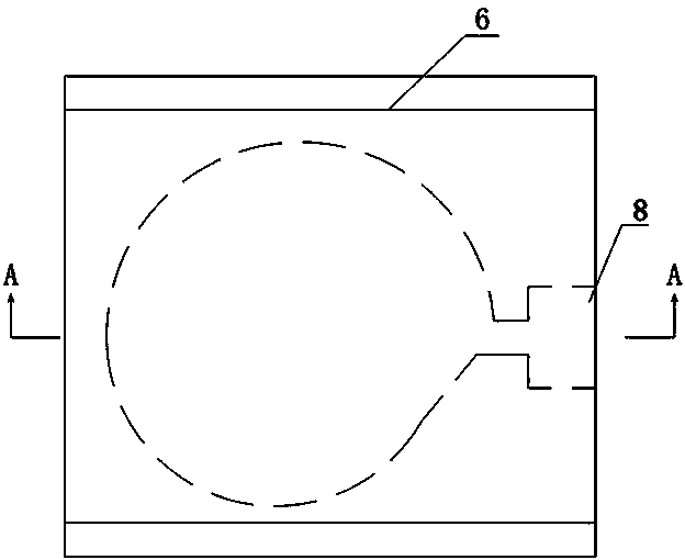
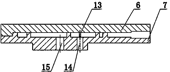
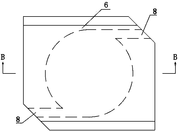
[0023] Such as figure 1 As shown, the automatic phase selection control valve includes a base pipe 1, and the outside of the base pipe 1 is sequentially set with an end cover 2, an outer ring sleeve 3 and a screen pipe 4 along the direction from front to back, and the end cover 2 is tightly connected with the base pipe 1 , in this implementation, the end cap 2 is welded to the base pipe 1, and a sealing ring is provided between the cylindrical inner wall of the end cap 2 and the outer surface of the base pipe 1, and the front end of the outer ring sleeve 3 and the rear end of the end cap 2 Tightly connected, the front end of the screen pipe 4 is connected to the rear end of the outer ring sleeve 3, and a swirl restrictor 5 is installed in the gap between the outer ring sleeve 3 and the base pipe 1. ...


PUM


Abstract

The invention discloses an automatic phase selection control valve. The automatic phase selection control valve comprises a base pipe (1); the outer portion of the base pipe (1) is sleeved with an end cover, an outer loop (3) and a screen pipe (4); a rotational flow restrictor (5) is arranged between the outer loop (3) and the base pipe (1); a lower end cover (7) of the rotational flow restrictor (5) is provided with a separation cavity (10) and a water storage cavity (12); a water nozzle (13) for being communicated with the water storage cavity (12) is arranged on the side wall of the separation cavity (10); and a base pipe liquid outlet (16) which is communicated with an oil nozzle (14) of the separation cavity (10) and a water outlet (15) of the water storage cavity (12) is formed in the base pipe (1). The automatic phase selection control valve has the beneficial effects that liquid can be differentiated to enable oil and water to be automatically separated; output of water is limited; the section is balanced, and the heel and toe effect is removed; the annular flow influence is removed, and the service life of an oil and gas well is prolonged; the recovery efficiency of a horizontal well control reservoir is improved; and the control valve is suitable for side / bottom water oil storage with the high heterogeneity.

Description

technical field [0001] The invention relates to an automatic water control tool for oil exploitation, in particular to a swirl type automatic phase selection control valve. Background technique [0002] As an advanced technology for oil and gas field development, horizontal wells are widely used in thin-bed reservoirs, bottom water reservoirs, fractured reservoirs, heavy oil reservoirs, and marine shallow and deep water reservoirs. The development of horizontal wells is to increase oil well production and economic benefits of oil field development by expanding the drainage area of ​​oil layers. Due to the long horizontal section, when developing a homogeneous and single oil layer, the existence of wellbore friction and unbalanced pressure difference makes the two ends of the horizontal section The high liquid production intensity and the low intermediate liquid production intensity lead to a very unbalanced contribution rate of each section of the horizontal well. As the pro...

Claims


Application Information

Patent Timeline
Patent Type & Authority Applications(China)
IPC IPC(8): E21B34/06
CPCE21B34/06E21B43/32E21B43/38
Inventor 李海涛阳明君王永清罗伟朱世琰
Owner SOUTHWEST PETROLEUM UNIV
Why Eureka
Try Eureka