Ionosphere propagation characteristic based phase diameter disturbance suppression method

A technology of phase disturbance and propagation characteristics, applied to radio wave measurement systems, instruments, etc., can solve problems such as limited suppression and failure, and achieve the effect of wide application conditions, phase disturbance suppression, and obvious suppression effect

Active Publication Date: 2015-03-04
HARBIN INST OF TECH
View PDF4 Cites 13 Cited by
  • Summary
  • Abstract
  • Description
  • Claims
  • Application Information

AI Technical Summary

Problems solved by technology

[0004] The purpose of the present invention is to propose a method for suppressing ionospheric phase path disturbance based on ionospheric propagation characteristics, so as to solve the problem that the existing ionospheric phase path disturbance suppression method suppresses ionospheric phase path disturbance from the perspective of signal processing, and the suppression effect is very limited. , or even failure

Method used


Image

  • Ionosphere propagation characteristic based phase diameter disturbance suppression method
  • Ionosphere propagation characteristic based phase diameter disturbance suppression method
  • Ionosphere propagation characteristic based phase diameter disturbance suppression method

Examples


specific Embodiment approach 1

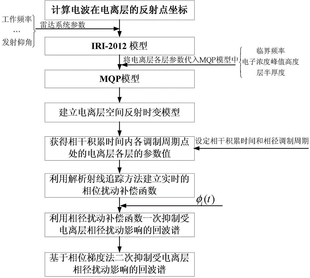
[0024] Embodiment 1: A method for suppressing phase disturbance based on ionospheric propagation characteristics described in this embodiment includes the following steps:

[0025] Step 1, calculating the coordinates of the reflection point of the radio wave in the ionosphere;

[0026] Step 2, establishment of ionospheric space reflection time-varying model;

[0027] In order to solve the problem of low accuracy of the IRI model and the inconvenience of obtaining parameters from the MQP model, a time-varying ionospheric reflection model was obtained by hybrid modeling of the International Reference Ionosphere Model (IRI-2012) and the Multi-Quasi-Parabolic Model (MQP), That is, the real-time changing parameter critical frequency f of each layer of the ionosphere in the reflection area is calculated by the IRI-2012 model m , electron concentration peak height r m and layer half-thickness y m ) into the MQP model to establish a time-varying model of ionospheric space reflectio...

specific Embodiment approach 2

[0091] Specific embodiment two: the difference between this embodiment and specific embodiment one is: the calculation process of the reflection point coordinates described in step one is:

[0092] According to the coordinates of the transmitter and the center coordinates of the detection area, the coordinates of the reflection point are calculated by the following formula:

[0093] N lon = T lon + R lon 2 , N lat = T lat + R lat 2

[0094] Among them, N lon and N lat are the longitude and latitude of the reflection point, T lon and T lat are the latitude and longitude of the t...

specific Embodiment approach 3

[0095] Specific implementation mode three: the difference between this implementation mode and specific implementation mode one or two is: the establishment process of the reflection time-varying model described in step two is:

[0096] According to the specific system layout and parameter requirements of the sky-wave radar, input the working time, working frequency, launch elevation angle, launch azimuth angle, and reflection point coordinates into the IRI-2012 model, and obtain the critical frequency of each layer of the ionosphere through the IRI-2012 model f m , electron concentration peak height r m and layer half-thickness y m Finally, it is passed to the MQP model, where m is the number of layers of the ionosphere, so as to complete the hybrid modeling of MQP and IRI-2012, and obtain the ionospheric spatial reflection time-varying model.


PUM


Abstract

The invention provides an ionosphere propagation characteristic based phase diameter disturbance suppression method and belongs to the radar signal processing technical field. The problem that the suppression effect is limited and even fails when the disturbance suppression is performed on the ionosphere phase diameter by the existing ionosphere phase diameter disturbance suppression method from the perspective of signal processing is solved. According to the technical scheme, the Ionosphere propagation characteristic based phase diameter disturbance suppression method comprises performing the hybrid modeling on an international reference ionosphere model and an MQP (Multi-Quasi Parabolic) model to obtain an ionosphere space reflection time-varying parameter model; deriving a phase path calculation analytic expression of the MQP model by a ray tracing method on the basis of the electron concentration profile of ionosphere space reflection time-varying parameter model and obtaining change values of a phase path along with the time after the repeated operation at different moments; performing the suppression on the back wave spectrum with the ionosphere phase diameter disturbance through a phase disturbance compensation curve obtained through fitting by a least square method and finally obtaining the suppressed ionosphere back wave spectrum. The Ionosphere propagation characteristic based phase diameter disturbance suppression method is suitable for the processing on the broadening sea clutter spectrum with the ionosphere phase diameter disturbance under a high-frequency sky wave radar.

Description

technical field [0001] The invention relates to an ionospheric phase path disturbance suppression method for high-frequency sky wave radar, in particular to a phase path disturbance suppression method based on ionospheric propagation characteristics, and belongs to the technical field of radar signal processing. Background technique [0002] Sky-wave over-the-horizon radar (OTHR) works in the high-frequency short-wave band, and uses the ionosphere as its main transmission medium to complete long-distance communication, over-the-horizon detection, and large-scale navigation activities. Its detection distance is not limited by the curvature of the earth. The detection distance is long and the coverage area is large. However, the ionosphere itself is a propagation medium with complex characteristics such as anisotropy, inhomogeneity, and dynamic time-varying. This layered structure and non-stationary characteristics make the phase path of the short-wave signal propagating in it...

Claims


Application Information

Patent Timeline
Patent Type & Authority Applications(China)
IPC IPC(8): G01S7/36
CPCG01S7/36
Inventor 位寅生李亚军朱永鹏许荣庆尚超
Owner HARBIN INST OF TECH
Why Eureka
Try Eureka